
User Manual Instruction Manual

2-20
GV6000 AC Drive User Manual
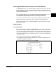
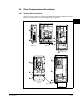
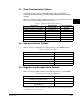
2.6 Drive Connections
Figure 2.6 shows the locations of the connectors used to set up and operate the drive.
Table 2.10 identifies the drive connections shown with the corresponding number in
figure 2.6.
Figure 2.6 – Drive Connections (Frame 0)
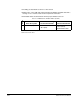
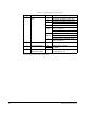
Table 2.10 – Drive Connection Descriptions
Number Connector Description
➊
DPI Port 1 OIM connection.
➋
DPI Port 2 Cable connection for handheld and remote options.
➌
DPI Port 3 or 2 Splitter cable connected to DPI Port 2 provides
additional port.
➍
DPI Port 5 Cable connection for optional communications module.
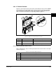
BR1
BR2
DC+
DC–
PE
U/T1
V/T2
W/T3
R/L1
S/L2
T/L3
Optional
Communications
Module
Use 75C Wire Only
#10-#14 AWG
Torque to 7 in-lbs
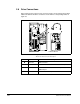
!
DANGER
2
1
o
r
3
➊
➋
➍
➌
Frame 0 Shown