
User Manual Instruction Manual

13-74
GV6000 AC Drive User Manual
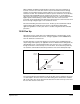
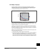
13.25.8 Temperature Display
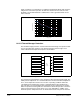
The Drive’s temperature is measured (NTC in the IGBT module) and displayed as a
percentage of drive thermal capacity in Drive Temp (218). This parameter is
normalized to the thermal capacity of the drive (frame dependent) and displays
thermal usage in % of maximum (100% = drive Trip). A test point, “Heatsink
temperature” is available to read temperature directly in degrees C, but cannot be
related to the trip point since “maximums” are only given in %. The IGBT temperature
shown in Figure 13-20 is used only for internal development and is not provided to the
user.
13.25.9 Low Speed Operation
When operation is below 4 Hz, the duty cycle is such that a given IGBT will carry more
of the load for a while and more heat will build up in that device. The thermal manager
will increase the calculated IGBT temperature at low output frequencies and will cause
corrective action to take place sooner.
When the drive is in current limit the output frequency is reduced to try to reduce the
load. This works fine for a variable torque load, but for a constant torque load reducing
the output frequency does not lower the current (load). Lowering current limit on a CT
load will push the drive down to a region where the thermal issue becomes worse. In
this situation the thermal manager will increase the calculated losses in the power
module to track the worst case IGBT. For example, if the thermal manager normally
provides 150% for 3 seconds at high speeds, it may only provide 150% for one second
before generating a fault at low speeds.
If operating at 60Hz 120%, lowering the current limit may cause a fault sooner than
allowing the drive to continue to operate. In this case the user may want to disable
current limit fold back.
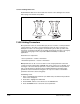
13.26 Droop
Droop is used to “shed” load and is usually used when a soft coupling of two
motors is present in an application. The master drive speed regulates and the follower
uses droop so it does not “fight” the master. The input to the droop block is the
commanded motor torque. The output of the droop block reduces the speed
reference. Droop RPM @ FLA (152) sets the amount of speed, in RPM, that the speed
reference is reduced when at full load torque. For example, when Droop RPM @ FLA
(152) is set to 50 RPM and the drive is running at 100% rated motor torque, the droop
block would subtract 50 RPM from the speed reference.
13.27 Flux Braking
You can use flux braking to stop the drive or to shorten the deceleration time to a
lower speed. Other methods of deceleration or stopping may perform better
depending on the motor and the load.
To enable flux braking:
1. Bus Reg Mode A, B (161, 162) must be set to “1” Adjust Freq to enable the bus
regulator.
2. Flux Braking (166) must be set to 1 “Enabled”.
FV
FV