
User Manual Instruction Manual

13-70
GV6000 AC Drive User Manual
13.24 DC Bus Voltage/Memory
DC Bus Voltage (12) is a measurement of the instantaneous value. DC Bus Memory
(13) is a heavily filtered value or “nominal” bus voltage. Just after the pre-charge relay
is closed during initial power-up bus pre-charge, bus memory is set equal to bus
voltage. Thereafter it is updated by ramping at a very slow rate toward Vbus. The
filtered value ramps at approximately 2.4V DC per minute (for a 480V AC drive).
Bus memory is used as the base line to sense a power loss condition. If the drive
enters a power loss state, the bus memory will also be used for recovery (i.e.
pre-charge control or inertia ride through upon return of the power source) upon return
of the power source. Update of the bus memory is blocked during deceleration to
prevent a false high value caused by a regenerative condition.
13.25 Drive Overload
The drive thermal overload has two primary functions. The first requirement is to make
sure the drive is not damaged by abuse. The second is to perform the first in a manner
that does not degrade the performance, as long the drive temperature and current
ratings are not exceeded.
The purpose of the drive overload feature is to protect the power structure from abuse.
Any protection for the motor and associated wiring is provided by a Motor Thermal
Overload feature.
The drive will monitor the temperature of the power module based on a measured
temperature and a thermal model of the IGBT. As the temperature rises the drive may
lower the PWM frequency to decrease the switching losses in the IGBT. If the
temperature continues to rise, the drive may reduce current limit to try to decrease the
load on the drive. If the drive temperature becomes critical the drive will generate a
fault.
If the drive is operated in a low ambient condition the drive may exceed rated levels of
current before the monitored temperature becomes critical. To guard against this
situation the drive thermal overload also includes an inverse time algorithm. When this
scheme detects operation beyond rated levels, current limit may be reduced or a fault
may be generated.
13.25.1 Operation
The drive thermal overload has two separate protection schemes, an overall RMS
protection based on current over time, and an IGBT junction thermal manager based
on measured power module temperature and operating conditions. The drive may fold
back current limit when either of these methods detects a problem.
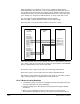
13.25.2 Overall RMS Protection
The overall RMS protection makes sure the current ratings of the drive are not
exceeded. The lower curve in Figure 13-18 shows the boundary of normal-duty
operation. In normal duty, the drive is rated to produce 110% of rated current for 60
seconds, 150% of rated current for three seconds, and 165% of rated current for 100
milliseconds. The maximum value for current limit is 150% so the limit of 165% for 100
milliseconds should never be crossed. If the load on the drive exceeds the level of