
User Manual Instruction Manual

About the Drive
2-19
2.5.2 I/O Control Cassette
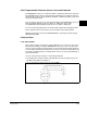
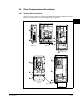
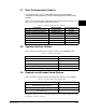
Figure 2.5 shows I/O Control Cassette and its terminal block locations. Each GV6000
is provided with a removable I/O Cassette. The I/O cassette is a plastic case which
houses the regulator, input/output, and encoder electronics. Table 2.8 identifies the
drive connections shown with the corresponding number in figure 2.5.
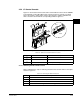
2.5.2.1 Removing the I/O Control Cassette
Table 2.9 identifies the steps for removing the I/O Control Cassette. Refer to the alpha
markers in figure 2.5.
Figure 2.5 – I/O Control Cassette and Terminal Blocks (Frame 0 Shown)
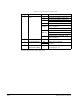
Table 2.8 – I/O Cassette and Terminal Block Locations
Number Name Description
➊
I/O Cassette Removable I/O Cassette
➋
I/O Terminal Block Signal and control connections
➌
Encoder Terminal Block Encoder power and signal connections
B
R
1
BR2
D
C
+
D
C
-
PE
U
/T
1
V
/T2
W
/T
3
R
/L
1
L
2
➌
➋
➊
B
A
C
B
D
Pin 1
Detail
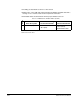
Table 2.9 – Removing the I/O Control Cassette
Step Description
A Disconnect the two cable connectors.
B Loosen the two screws latches.
C Slide the cassette out.
D Remove screws securing cassette cover to gain access to the boards.