
User Manual Instruction Manual

13-68
GV6000 AC Drive User Manual
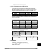
tables, depending on configuration. A user enters a parameter number into the
Datalink parameter. The value that is in the corresponding output data table word in
the controller is then transferred to the parameter whose number has been placed in
the Datalink parameter. The following example demonstrates this concept. The object
of the example is to change Accel and Decel times “on the fly” under PLC control.
The user makes the following GV6000 drive parameter settings:
Data In A1(300) = 140 (the parameter number of Accel Time 1(140))
Data In A2 (301) = 142 (the parameter number of Decel Time 1 (142))
In the PLC data Table, the user enters Word 3 as a value of 100 (10.0 Secs) and word
4 as a value of 133 (13.3 seconds). On each I/O scan, the parameters in the GV6000
drive are updated with the value from the data table:
Accel Time1 (140) = 10.0 seconds (value from output image table Word 3)
Decel Time1 (142) = 13.3 seconds (value from output image table Word 4).
Any time these values need to be changed, the new values are entered into the data
table, and the parameters are updated on the next PLC I/O scan.
13.23.1 Rules for Using Datalinks
1. 1. A Datalink consists of 4 words, 2 for Datalink x IN and 2 for Datalink x Out. They
cannot be separated or turned on individually.
2. Parameter settings in the drive determine the data passed through the Datalink
mechanism
3. When you use a Datalink to change a value, the value is not written to the
Non-Volatile Storage (EEprom memory). The value is stored in volatile memory
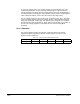
Programmable
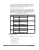
Controller
I/O Image Table
Remote I/O
Communication
Module
Adjustable Frequency
AC Drive
Block Transfer
Logic Command
Analog Reference
WORD 3
WORD 4
WORD 5
WORD 6
WORD 7
Output Image
Data In A1
Data In A2
Data Out A1
Data Out A2
300
301
310
311
Parameter/Number
Block Transfer
Logic Status
Analog Feedback
WORD 3
WORD 4
WORD 5
WORD 6
WORD 7
Input Image
Datalink A
Datalink A