
User Manual Instruction Manual

Application Notes
13-67
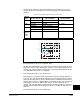
• Thermal Manager
1. Instantaneous Overcurrent - This is a feature that instantaneously trips or faults the
drive if the output current exceeds this value. The value is fixed by hardware and is
typically 250% of drive rated amps. The Fault code for this feature is F12 “HW
Overcurrent.” This feature cannot be defeated or mitigated.
2. Software Instantaneous Trip - There could be situations where peak currents do
not reach the F12 “HW Overcurrent” value and are sustained long enough and high
enough to damage certain drive components. If this situation occurs, the drives
protection scheme will cause an F36 “SW Overcurrent” fault. The point at which
this fault occurs is fixed and stored in drive memory.
3. Software Current Limit - This is a software feature that selectively faults the drive or
attempts to reduce current by folding back output voltage and frequency if the
output current exceeds this value. The Current Lmt Val (148) parameter is
programmable between approximately 25% and 150% of drive rating. The reaction
to exceeding this value is programmable with [Shear Pin Fault]. Enabling this
parameter creates an F63 “Shear Pin Fault.” Disabling this parameter causes the
drive to use Volts/Hz fold back to try and reduce load. The frequency adjust or fold
back operation consists of two modes. In the primary mode of current limit
operation, motor phase current is sampled and compared to the Current Limit
setting in the Current Lmt Val (148). If a current “error” exists, error is scaled by an
integral gain and fed to the integrator. The output of this integrator is summed with
the proportional term and the active speed mode component to adjust the output
frequency and the commanded voltage. The second mode of current limit
operation is invoked when a frequency limit has been reached and current limit
continues to be active. At this point, a current regulator is activated to adjust the
output voltage to limit the current. When the current limit condition ceases or the
output voltage of the current regulator attempts to exceed the open loop voltage
commands, control is transferred to the primary current limit mode or normal ramp
operation.
4. Overload Protection I
2
T - This is a software feature that monitors the output current
over time and integrates per IT. The base protection is 110% for 1 minute or the
equivalent I
2
T value (i.e. 150% for 3 seconds, etc.). If the IT integrates to
maximum, an F64 “Drive Overload” fault will occur. The approximate integrated
value can be monitored via the Drive OL Count (219) parameter.
5. Heatsink Temperature Protection - The drive constantly monitors the heatsink
temperature. If the temperature exceeds the drive maximum, a “Heatsink
OvrTemp” fault will occur. The value is fixed by hardware at a nominal value of 100
degrees C. This fault is generally not used for overcurrent protection due to the
thermal time constant of the heatsink. It is an overload protection.
6. Thermal manager (see Drive Overload in Section 13.25).
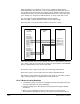
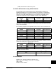
13.23 Datalinks
A Datalink is one of the mechanisms used by GV6000 drives to transfer data to and
from a programmable controller. Datalinks allow a parameter value to be changed
without using an Explicit Message or Block Transfer. Datalinks consist of a pair of
parameters that can be used independently for 16 bit transfers or in conjunction for 32
bit transfers. Because each Datalink consists of a pair of parameters, when enabled,
each Datalink occupies two 16 or 32-bit words in both the input and output image