
User Manual Instruction Manual

Application Notes
13-65
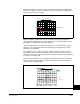
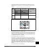
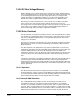
The bus voltage regulation setpoint is determined off of bus memory (a means to
average DC bus over a period of time). The following graph and tables describe the
operation.
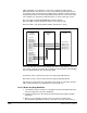
If Bus Reg Mode A (161) is set to “Dynamic Brak”
The Dynamic Brake Regulator is enabled. In “Dynamic Brak” mode the Bus Voltage
Regulator is turned off. The “DB Turn On” and turn off curves apply (Table 13-5). For
example, with a DC Bus Memory at 684V DC, the Dynamic Brake Regulator will turn
on at 750V DC and turn back off at 742V DC.
If Bus Reg Mode A (161) is set to “Both-Frq 1st”
Both regulators are enabled, and the operating point of the Bus Voltage Regulator is
lower than that of the Dynamic Brake Regulator. The Bus Voltage Regulator setpoint
follows the “Bus Reg Curve 2” below a DC Bus Memory of 650V DC and follows the
“DB Turn Off” curve above a DC Bus Memory of 650V DC (Table 13-5). The Dynamic
Brake Regulator follows the “DB Turn On” and turn off curves (Table 13-5). For
example, with a DC Bus Memory at 684V DC, the Bus Voltage Regulator setpoint is
742V DC and the Dynamic Brake Regulator will turn on at 750V DC and back off at
742V DC.
If Bus Reg Mode A (161) is set to “Adjust Freq”
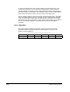
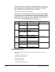
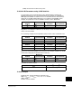
Table 13.4 – Bus Voltage Regulation Setpoint Determination 1
Voltage
Class DC Bus Memory DB on Setpoint DB Off Setpoint
240 <342 VDC 375 VDC On -4 VDC
>342 VDC Memory +33 VDC
480 <685 VDC 750 VDC On -8 VDC
>685 VDC Memory +65 VDC
600 <856 VDC 937 VDC On -10 VDC
>856 VDC Memory +81 VDC
600/690V
Frames 5
and 6
only
<983 VDC 1076 VDC On -11 VDC
320 360 460 484 528 576
453
509
650
685
750
815
880
AC Volts
DC Volts
DB Turn On
DB Turn Off
Bus Memory
Bus Reg Curve #2
Bus Reg Curve #1