
User Manual Instruction Manual

13-64
GV6000 AC Drive User Manual
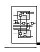
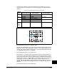
The derivative term senses a rapid rise in the bus voltage and activates the bus
regulator prior to actually reaching the bus voltage regulation set point Vreg. The
derivative term is important since it minimizes overshoot in the bus voltage when bus
regulation begins thereby attempting to avoid an over-voltage fault. The integral
channel acts as the acceleration or deceleration rate and is fed to the frequency ramp
integrator. The proportional term is added directly to the output of the frequency ramp
integrator to form the output frequency. The output frequency is then limited to a
maximum output frequency.
Bus voltage regulation is the highest priority of the three components of this controller
because minimal drive current will result when limiting the bus voltage and therefore,
current limit will not occur.
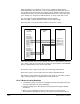
The user selects the bus voltage regulator using the Bus Reg Mode parameters. The
available modes include:
• Disabled
• Frequency regulation
• Dynamic braking
• Dynamic braking as the primary regulation means with frequency regulation as a
secondary means
• Frequency regulation as the primary regulation means with dynamic braking as a
secondary means
!
ATTENTION: The “adjust freq” portion of the bus regulator function
is extremely useful for preventing nuisance overvoltage faults
resulting from aggressive decelerations, overhauling loads, and
eccentric loads. It forces the output frequency to be greater than
commanded frequency while the drive's bus voltage is increasing
towards levels that would otherwise cause a fault; however, it can
also cause either of the following two conditions to occur.
1. Fast positive changes in input voltage (more than a 10%
increase within 6 minutes) can cause uncommanded positive
speed changes; however an “OverSpeed Limit” fault will occur if
the speed reaches [Max Speed] + [Overspeed Limit]. If this
condition is unacceptable, action should be taken to 1) limit
supply voltages within the specification of the drive and, 2) limit
fast positive input voltage changes to less than 10%. Without
taking such actions, if this operation is unacceptable, the “adjust
freq” portion of the bus regulator function must be disabled (see
parameters 161 and 162).
2. Actual deceleration times can be longer than commanded
deceleration times; however, a “Decel Inhibit” fault is generated
if the drive stops decelerating altogether. If this condition is
unacceptable, the “adjust freq” portion of the bus regulator must
be disabled (see parameters 161 and 162). In addition,
installing a properly sized dynamic brake resistor will provide
equal or better performance in most cases.
Note: These faults are not instantaneous and have shown test
results that take between 2 and 12 seconds to occur.