
User Manual Instruction Manual

13-62
GV6000 AC Drive User Manual
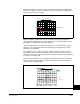
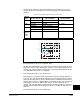
To avoid over-voltage faults, a bus voltage regulator is incorporated as part of the
acceleration/deceleration control. As the bus voltage begins to approach the bus
voltage regulation point (Vreg), the bus voltage regulator increases the magnitude of
the output frequency and voltage to reduce the bus voltage. The bus voltage regulator
function takes precedence over the other two functions. See Figure13-17.
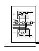
The bus voltage regulator is shown in the lower one-third of Figure 13-17. The inputs
to the bus voltage regulator are the bus voltage, the bus voltage regulation set point
Vreg, proportional gain, integral gain, and derivative gain. The gains are intended to
be internal values and not parameters. These will be test points that are not visible to
the user. Bus voltage regulation is selected by the user in the Bus Reg Mode
parameter.
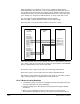
13.21.1 Operation
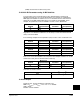
Bus voltage regulation begins when the bus voltage exceeds the bus voltage
regulation set point Vreg and the switches shown in Figure 13-17 move to the
positions shown in Table 13-2.
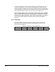
Table 13.3 – Switch Positions for Bus Regulator Active
SW 1 SW 2 SW 3 SW 4 SW 5
Bus Regulation Limit Bus Reg Open Closed Don’t Care