
User Manual Instruction Manual

13-60
GV6000 AC Drive User Manual
13.20.6.3 Parameter Controlled Analog Output
Enables the analog outputs to be controlled by Datalinks to the drive.
Example
Analog Output 1 controlled by DataLink C1. Output 0-10V DC with DataLink values of
0-10000.
Setup
• Data In C1(304) = 377 “Anlg Out1 Setpt”
• Analog Out1 Sel (342) = 24 “Parameter Control”
• Analog Out1 Hi (343) = 10.000 Volts
• Analog Out1 Lo (344) = 0.000 Volts
The device that writes to DataLink C1 now controls the voltage output of Analog Out1.
For example: 2500 = 2.5V DC, 5000 = 5.0V DC, 7500 = 7.5V DC.
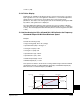
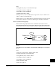
13.21 Bus Regulation
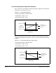
Some applications, such as the hide tanning shown here, create an intermittent
regeneration condition. When the hides are being lifted (on the left), motoring current
exists. However, when the hides reach the top and fall onto a paddle, the motor
regenerates power back to the drive, creating the potential for a nuisance overvoltage
trip.
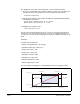
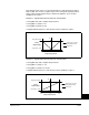
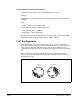
When an AC motor regenerates energy from the load, the drive DC bus voltage
increases unless there is another means (dynamic braking chopper/resistor, etc.) of
dissipating the energy
Motoring Regenerating