
User Manual Instruction Manual

2-18
GV6000 AC Drive User Manual
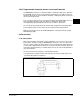
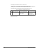
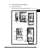
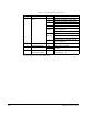
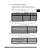
Table 2.7 – Power Terminal Block Locations Table
Number Name Frame Description
➊
Power Terminal
Block
0 & 1 Input Power and Motor Connections
2 Input Power and Motor Connections
3 Input Power and Motor Connections
BR1, 2 Terminals
4 Input Power and Motor Connections
5
(75 HP)
Input power, BR 1, 2, DC+, DC- and
motor connections
PE
5
(100 HP)
Input Power, DC+, DC- and motor
BR1, 2 Terminals
PE
6 Input power, DC+, DC-, BR1, 2, PE,
motor connections
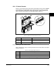
➋
SHLD Terminal 0-6 Terminating point for wiring shields
➌
Aux Terminal Block 0-4 Auxiliary Control Voltage
PS+, PS-
1
1.External control power: UL Installation - 300 VDC, +/- 10%, Non UL Installation - 270-600 VDC, +/- 10%;
0-3 Frame - 40 W, 165 mA, 5 Frame - 80 W, 90 mA.
5-6
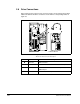
➍
Fan Terminal Block
(Common Bus Only)
5-6 User Supplied Fan Voltage
(See section 3.1.1.4.)