
User Manual Instruction Manual

13-54
GV6000 AC Drive User Manual
This deadband, as it relates to the analog input, can be calculated as follows:
1. The ratio of analog input volts to frequency (Volts/Hz) needs to be calculated. The
voltage span on the analog input is 10 volts. The frequency span is 60 Hz.
2. Determine the frequency span between the Minimum and Maximum Speed limits
and Speed Ref A Hi and Lo.
3. Multiply by the Volts/Hertz ratio
Therefore the command frequency from 0 to 2.5 volts on the analog input will be 15
Hz. After 2.5 volts, the frequency will increase at a rate of 0.16667 volts per hertz to
7.5 volts. After 7.5 volts on the analog input the frequency command will remain at 45
Hertz.
Example 2:
Consider the following setup:
• Anlg In Config (320), bit 0 = “0” (voltage)
• Speed Ref A Sel (90) = “Analog In 1”
• Analog In1 Hi (322) = 10V
• Analog In1 Lo (323) = 0V
• Speed Ref A Hi (91) = 50hz
• Speed Ref A Lo (92) = 0hz
• Maximum Speed (82) = 45hz
• Minimum Speed (81) = 15hz
The only change from Example 1 is the Speed Ref A Hi (91) is changed to 50 Hz.
10 Volts/60 Hz = 0.16667 Volts/Hz
Speed Ref A Hi (91) – Maximum Speed (82) = 60 – 45 = 15 Hz and . . .
Minimum Speed (81) – Speed Ref A Lo (92) = 15 – 0 = 15 Hz.
15 Hz x 0.16667 Volts/Hz = 2.5 Volts
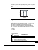
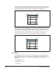
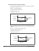
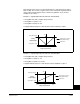
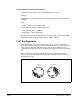
Motor Operating Range
Maximum Speed (91)Minimum Speed (81)
Command Frequency
Slope defined by (Analog Volts)/(Command Frequency)
Frequency Deadband
Frequency Deadband
15 Hz 45 Hz 50 Hz0 Hz
Speed Ref A Lo (92) Speed Ref A Hi (91)
10V
0V
Analog In1 H (322)]
Analog In1 Lo (323)
0-3 Volts 9-10 Volts