
User Manual Instruction Manual

Application Notes
13-53
• Trim Lo (120)
13.19.7 Value Display
Parameters are available in the Monitor Group to view the actual value of an analog
input regardless of its use in the application. Whether it is a current limit adjustment,
speed reference or trim function, the incoming value can be read via these
parameters. The values of the analog inputs can also be viewed by pressing the DISP
key until the analog I/O screen is displayed.
The value displayed includes the input value plus any factory hardware calibration
value, but does not include scaling information programmed by the user (i.e. Analog In
1 Hi/Lo). The units displayed are determined by the associated configuration bit (Volts
or mA)
13.19.8 How Analog Inx Hi/Lo & Speed Ref A Hi/Lo Scales the Frequency
Command Slope with Minimum/Maximum Speed
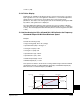
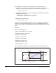
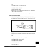
Example:
Consider the following setup:
• Anlg In Config (320), bit 0 = “0” (voltage)
• Speed Ref A Sel (90) = “Analog In 1”
• Analog In1 Hi (322) = 10V
• Analog In1 Lo (323) = 0V
• Speed Ref A Hi (91) = 60 Hz
• Speed Ref A Lo (92) = 0 Hz
• Maximum Speed (82) = 45 Hz
• Minimum Speed (81) = 15 Hz
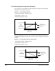
This operation is similar to the 0-10 volts creating a 0-60 Hz signal until the minimum
and maximum speeds are added. Minimum Speed (81) and Maximum Speed (82)
limits will create a command frequency deadband.
Motor Operating Range
Command Frequency
15 Hz 45 Hz 60 Hz0 Hz
Frequency Deadband
Slope defined by (Analog Volts)/(Command Frequency)
Frequency Deadband
7.5-10 Volts0-2.5 Volts
Speed Ref A Lo (92) Speed Ref A Hi (91)
10V
0V
Analog In1 Hi (322)
Analog In1 Lo (323)
Maximum Speed (82)Minimum Speed (81)