
User Manual Instruction Manual

Application Notes
13-51
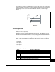
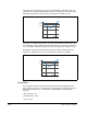
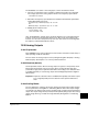
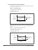
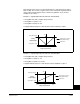
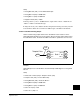
The square root function is scaled such that the input range is the same as the output
range. For example, if the input is set up as a unipolar voltage input, then the input and
output ranges of the square root function will be 0 to 10 volts, as shown in figure
below.
13.19.5 Signal Loss
Analog In 1, 2 Loss (324, 327)
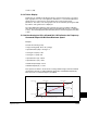
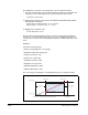
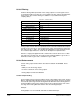
Signal loss detection can be enabled for each analog input. The [Analog In x Loss]
parameters control whether signal loss detection is enabled for each input and defines
what action the drive will take when loss of any analog input signal occurs.
One of the selections for reaction to signal loss is a drive fault, which will stop the
drive. All other choices make it possible for the input signal to return to a usable level
while the drive is still running.
• Hold input
• Set input Lo
• Set input Hi
• Goto Preset 1
• Hold Output Frequency
2
4
6
8
10
2046
Input (Volts)
Output (Volts)
810
Value Action on Signal Loss
0 Disabled (default)
1Fault
2 Hold input (continue to ise last frequency command)
3 Set Input Hi - use Minimum Speed (81) as frequency command
4 Set Input Lo - use Maximum Speed (82) as frequency command
5 Use Preset 1(101) as frequency command
6 Hold Out Freq (maintain last outout frequency)