
User Manual Instruction Manual

Application Notes
13-39
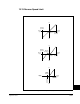
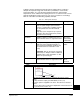
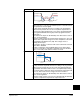
Ramp to Hold
This method combines two of the methods above. It uses drive
output reduction to stop the load and DC injection to hold the load at
zero speed once it has stopped.
On Stop, drive output will decrease according to the programmed
pattern from its present value to zero. The pattern may be linear or
squared. The output will decrease to zero at the rate determined by
the programmed Maximum Freq (82) and the programmed active
Decel Time x.
The reduction in output can be limited by other drive factors such as
bus or current regulation.
When the output reaches zero 3 phase drive output goes to zero (off)
and the drive outputs DC voltage on the last used phase at the level
programmed in DC Brake Level (158). This voltage causes a
“holding” brake torque.
DC voltage to the motor continues until a Start command is reissued
or the drive is disabled.
If a Start command is reissued, DC Braking ceases and he drive
returns to normal AC. If an Enable command is removed, the drive
enters a “not ready” state until the enable is restored.
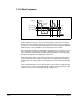
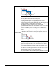
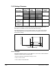
Fast Brake
This method uses drive output reduction to stop the load.
On Stop, the drive output will decrease according to the programmed
pattern from its present value to zero at the rate determined by the
programmed active Decel Time x. This is accomplished by lowering
the output frequency below the motor speed where regeneration will
not occur. This causes excess energy to be lost in the motor.
The reduction in output can be limited by other drive factors such as
bus or current regulation.
When the output reaches very near zero, DC brake will automatically
be used to complete the stop then the output is shut off.
Mode Description
DC
Hold Level
Time
Output Voltage
Output Voltage
Output Current
Output Current
Motor Speed
Output Voltage
Output Current
Motor Speed
Re-issuing a
Start Command
Stop
Command
Zero
Command
Speed
Stop
Command
Time
Output Voltage
Output Current
Motor Speed