
User Manual Instruction Manual

Application Notes
13-29
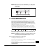
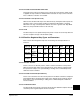
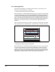
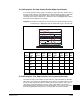
13.12.8 Example 2: Six Step Velocity Profile (Digital Input-Based)
In each step, the drive ramps at Step x AccelTime to Step x Velocity in the direction of
the sign of Step x Velocity until a digital input is detected. When the input is detected it
transitions to the next step in the profile. This continues through Digital Input #6
activating step 5. Step 5 is defined as a “Parameter Level” step. Digital Inputs used in
the profile must be defined as “Prof Input.”
Important: A transition is required to start each step. If the input is already true when
transitioning to a digital input step, the indexer will not go to the next step.
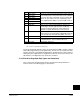
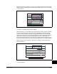
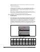
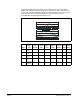
13.12.9 Example 3: Five Step Positioner with Incremental Encoder
The first three steps of this indexer are “Encoder Incr” steps followed by an “Encoder
Abs” step to zero and then an “End Hold Position” step. For each “Encoder Incr” step
the drive ramps at Step x AccelTime to Step x Velocity in the direction of the sign of
Step xValue. It then decelerates at the rate of Step x DecelTime to the position
programmed in Step x Value which sets the desired units of travel for the step. When
the value programmed in Step x Value is reached within the tolerance window
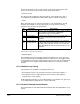
Figure 13.12 – Digital Input Example
Step #
Step x
Type
Step x
Velocity
Step x
Accel
Time
Step x
Decel
Time
Step x
Value
Step x
Dwell
Step x
Batch
Step x
Next
1 Digital
Input
300 0.5 0.5 3.00 0.00 1 2
2 Digital
Input
50 0.5 0.5 4.00 5.00 1 3
3 Digital
Input
-300 0.5 0.5 5.00 0.00 1 4
4 Digital
Input
-100 0.5 0.5 6.00 0.00 1 5
5 Param
Level
-50 0.5 0.5 701 0.00 1 6
6End NA NA 0.5 NA 0.00 NA NA
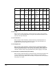
0
5
10
15
20
25
30
35
40
45
50
-350
-50
-150
-250
0
50
150
250
350
30 50 70 90 110 130 150 170
Step 1
Digital Input #4
Step 2
Step 3
Time
Step 4
Step 5
Note: Step 5 is a Parameter Level Step.
Step 6
Digital Input #6
5s
Dwell
Encoder Speed (415) Units Traveled (701) Current Step Dig In Status (216)Profile Status (700)
Digital Input #3
Digital Input #5
10