
User Manual Instruction Manual

13-22
GV6000 AC Drive User Manual
For Velocity Profiling, any motor control mode can be used. However, Sensorless
Vector or FVC Vector Control modes will offer the best performance.
• Direction Control
The drive must be configured to allow the profile to control the direction. This is
accomplished by setting Direction Mide (190) to “Bipolar” (default is “Unipolar.”)
• Limits
Many threshold values can affect the performance of the profile/indexer. To help
minimize the possibility of overshooting a position, ensure that the following
parameters are set for the best performance.
• Speed Regulator
The bandwidth of the speed regulator will affect the performance. If the connected
inertia is relatively high, the bandwidth will be low and therefore a bit sluggish. When
programming the acceleration and deceleration rates for each step, do not make them
too aggressive or the regulator will be limited and therefore overshoot the desired
position.
13.12.2 Position Loop Tuning
Two parameters are available for tuning the position loop.
• Pos Reg Filter (718) is a low pass filter at the input of the position regulator. •
• Pos Reg Gain (719) is a single adjustment for increasing or decreasing the
responsiveness of the regulator.
By default these parameters are set at approximately a 6:1 ratio(filter = 25, gain = 4). It
is recommended that a minimum ratio of 4:1 be maintained.
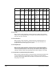
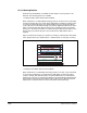
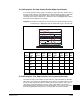
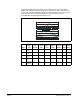
13.12.3 Profile Command Control Window
The profile/indexer is controlled with Profile Command (705). The bit definitions are as
follows:
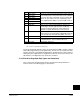
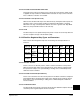
No. Parameter Description
153 Regen Power Limit Default is –50% and will likely require a greater negative
value. A brake or other means of dissipating
regenerative energy is recommended.
147 Current Lmt Sel By default these parameters are set to provide 150% of
drive rating. If lowered, the performance may be
degraded.
148 Current Lmt Sel
161
162
Bus Reg Mode A
Bus Reg Mode B
The default setting will adjust frequency to regulate the
DC Bus voltage under regenerative conditions. This will
most likely cause a position overshoot. To resolve this,
select “Dynamic Brak” and size the load resistor for the
application.
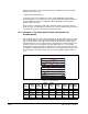
NA= Function not applicable to this step type