
User Manual Instruction Manual

13-20
GV6000 AC Drive User Manual
13.11 Limit Switches for Digital Inputs
The GV6000 includes digital input selections for decel and end limit switches. These
can be used for applications that use limit switches for decelerating near the end of
travel and then stopping at the end position. The end limit switch can also be used for
end limit stops as many hoists require. These inputs can be used with or without
Torque Proving enabled.
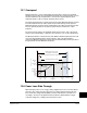
13.11.1 Decel Limit for Digital Inputs
Decel Limit is enabled by selecting “Decel Limit” as one of the digital inputs in Digital
In1-6 Select (361-366). When this input is “low” (opposite logic), the speed reference
command will change from the selected reference to the value in Preset Speed 1
(101). The deceleration rate will be based on the active deceleration time. This limit
will be enforced only in the direction the drive was running when the switch was
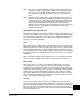
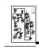
actived (momentarily or continuously, see “B” in Figure 13-7. The opposite direction
will still be allowed to run at the selected reference speed. No speed limitation will
occur between the limit switches (“A” in Figure 13-7).
Two different switches can be connected in series to one digital input to provide a
decel limit at both ends of of the application (i.e. lift, conveyer, etc.). With proper set
up, the drive will automatically apply the speed reduction based on the direction of the
load even though only one digital input is being used. See “B” in Figure 13-7.
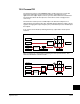
13.11.2 End Travel Limit for Digital Inputs
End Travel Limit is enabled by selecting “End Limit” as one of the digital inputs in
Digital In1-6 Select (361-366). A “low” at this input (opposite logic) will cause the drive
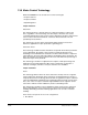
to do a fast decel (0.1 sec) and turn off. This Stop limit will be enforced only in the
direction the drive was running when the switch was activated (momentarily or
continuously, see “C” in Figure 13-7).
A Start command in the same direction will only allow 0 Hz to be commanded. A Start
in the opposite direction will allow motion with a speed command from the selected
speed reference If Torque Proving is Enabled, the drive will hold zero speed for a time
determined ZeroSpdFloat Time (605).
Two different input switches can be connected in series to one digital input to provide
an end limit at both ends of the application (e.g. lift, conveyer, etc.). With proper set up,
the drive will automatically apply the proper stopping based on the direction of the
load even though only one digital input is being used.
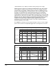
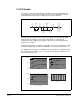
13.11.3 Limit Switch Set up
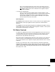
1. Move the load to a position between two decel switches (“A” in Figure 13-7).
2. Select the switches in Digital In1-6 Select (361-366). If switches are only used on
one end of travel, simply keep the load off of both switches when selecting Digital
In1-6 Select (361-366).