
User Manual Instruction Manual

13-18
GV6000 AC Drive User Manual
13.10 PI Enable
The output of the PI loop can be turned on (enables) or turned off (disabled). This
control allows the user to determine when the PI loop is providing part or all of the
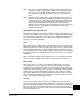
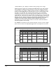
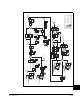
commanded speed. The logic for enabling the PI loop is shown below.
The drive must be running for the PI loop to be enabled. The loop will be disabled
when the drive is ramping to a stop (unless “Stop Mode” is configured in PI
Configuration (124)), jogging or the signal loss protection for the analog input(s) is
sensing a loss of signal.
If a digital input has been configured to “PI Enable,” two events are required to enable
the loop: the digital input must be closed AND bit 0 of PI Control (125) must be = 1.
If no digital input is configured to “PI Enable,” then only the Bit 0 = 1 condition must be
met. If the bit is permanently set to a “1”, then the loop will become enabled as soon
as the drive goes into “run.”
Drive
Running
Drive
Ramping
to Stop
Drive
Jogging
Bit 0 of
PI Control (125) = 1
(enabled)
PI Configuration (124)
Signal Loss
The Configured
Digital Input
is Closed
A Digital Input
is Configured
to PI Enable
"Enabled" Status
Digital Input
is Reflected
in PI Status (134)
Bit 0 = 1
The PI Loop
is Enabled
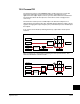
Bit 0 Bit 6
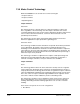
PI Enabled
Spd Cmd
PI Output
PI Pre-load Value
PI Pre-load Value = 0 PI Pre-load Value > 0
Pre-load to Command Speed
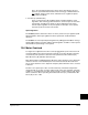
PI Enabled
Spd Cmd
PI Output
Start at Spd Cmd
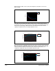
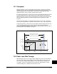
-100.0 -75.0 -50.0 -25.0 0.0 25.0 50.0 75.0 100.0
Normalized Feedback
Normalized SQRT(Feedback)
-100.0
-75.0
-50.0
-25.0
0.0
25.0
50.0
75.0
100.0