
User Manual Instruction Manual

13-16
GV6000 AC Drive User Manual
• DC Bus Memory (13) - displays a 6 minute running average of the voltage.
All drive reactions to power loss are based on DC Bus Memory (13). This averages
low and high line conditions and sets the drive to react to the average rather than
assumed values. For example, a 480V installation would have a 480V AC line and
produce a nominal 648V DC bus. If the drive were to react to a fixed voltage for line
loss detect, (i.e. 533V DC), then normal operation would occur for nominal line
installations. However, if a lower nominal line voltage of 440V AC was used, then
nominal DC bus voltage would be only 594V DC. If the drive were to react to the fixed
533V level (only –10%) for line loss detect, any anomaly might trigger a false line loss
detection. Line loss, therefore always uses the 6 minute average for DC bus voltage
and detects line loss based on a fixed percentage of that memory. In the same
example, the average would be 594V DC instead of 650V DC and the fixed
percentage, 27% for “Coast to Stop” and 18% for all others, would allow identical
operation regardless of line voltage.
The GV6000 can selectively use the same percentages or the user can set a trigger
point for line loss detect. The adjustable trigger level is set using Power Loss Level.
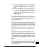
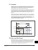
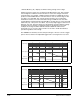
Figure 13.5 – Power Loss Mode = Coast
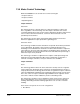
Figure 13.6 – Power Loss Mode = Decel
Nominal
73%
Bus Voltage
Motor Speed
Output Enable
Power Loss
Nominal
82%
Bus Voltage
Motor Speed
Output Enable
Power Loss