
User Manual Instruction Manual

Application Notes
13-11
Step 2. After the time period programmed in Brk Set Time (607) the drive will verify if
the brake is capable of holding torque. It will do this by ramping the torque
down at a rate set in TorqLim SlewRate (608). Note that the drive can be
started again at anytime without waiting for either of the above timers to
finish.
Step 3. While the torque is ramping down, the drive will perform a brake slip test. If
movement exceeds the limit set in BrkSlip Count (609) then an alarm is set
and the drive will start a brake slip procedure. The drive will allow the motor
to travel the distance programmed Brk Alarm Travel (610). Another slip test
will be performed and will repeat continuously until; A) the load stops
slipping, or B) the load reaches the ground. This feature keeps control of the
load and returns it to the ground in a controlled manner in the event of a
mechanical brake failure.
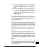
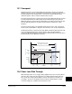
Speed Monitoring / Speed Band Limit
This routine is intended to fault the drive if the difference between the speed reference
and the encoder feedback is larger than the value set in Spd Dev Band (602) and the
drive is NOT making any progress toward the reference. SpdBand Integrat (603) sets
the time that the speed difference can be greater than the deviation band before
causing a fault and setting the brake.
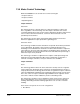
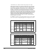
Float
Float is defined as the condition when the drive is holding the load at zero hertz while
holding off the mechanical brake. The float condition starts when the frequency drops
below the speed set in Float Tolerance (606). Float will stay active for a period of time
set by ZeroSpdFloatTime (605). If a digital input (parameters 361-366) is set to “Micro
Pos” (also Float) and it is closed, the Float condition will stay active and will disregard
the timer. This signal is also available through a communication device, see TorqProve
Setup (601).
When encoderless Torque Proving is enabled, the drive can not hold the load at zero
speed. Float Tolerance (606) will then define the speed at which the brake is set.
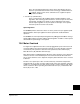
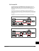
Micro Position
Micro Position refers to rescaling of the commanded frequency by a percentage
entered in MicroPos Scale % (611). This allows for slower operation of a lift which
provides an operator with better resolution when positioning a load. Micro Position is
activated only when the drive is running at or near zero speed. This can be initiated by
a digital input configured as Micro Pos or through a communication device (TorqProve
Setup) which is the same digital input which signals the float condition. To allow the
Micro Position digital input to change the speed command while the drive is running,
enter a “1” in Parameter 600, Bit 2 “MicroPosSel.” A “0” will require drive to reach zero
speed for micro position speed to become active.
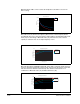
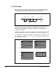
Fast Stop
Fast Stop is intended to stop the load as fast as possible then set the mechanical
brake. The Fast Stop can be initiated from a digital input or through a communication
device through [TorqProve Setup]. The difference from a normal stop is that the decel
time is forced to be 0.1 seconds. When the Torque Proving function is enabled, the
Float time is ignored at the end of the ramp. This feature can be used without enabling
the Torque Proving function.