
User Manual Instruction Manual

13-10
GV6000 AC Drive User Manual
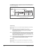
The GV6000 lifting application is mainly influenced by parameters 600 through 611 in
the Torque Proving group of the Application file. Figure 13.3 and the paragraphs that
follow describe programming.
Torque Proving
When the drive receives a start command to begin a lifting operation, the following
actions occur:
Step 1. The drive first performs a transistor diagnostic test to check for
phase-to-phase and phase-to-ground shorts. A failure status from either of
these tests will result in a drive fault and the brake relay will NOT be
energized (brake remains set).
Step 2. The drive will then provide the motor with flux as well as perform a check for
current flow through all three motor phases. This ensures that torque will be
delivered to the load when the mechanical brake is released. When torque
proving is enabled, open phase loss detection is performed regardless of the
setting of Bit 12 of Fault Config 1(238).
Step 3. If the drive passes all tests, the brake will be released and the drive will take
control of the load after the programmed time in Brk Release Time (604)
which is the typical mechanical release time of the brake.
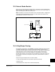
Brake Proving
When the drive receives a stop command to end a lifting operation, the following
actions occur:
Step 1. The brake is commanded closed when the speed of the motor reaches zero.
Figure 13.3 – Lifting/Torque Proving Application Programming
Torque
Prove Initiated
Brake
Released
Float
Initiated
Brake
Set
Brake
Slip Test
Run
Command
Run
Command Released
Drive Running
Run can be initiated anytime
All times between Drive Actions are programmable and can be made very small
(i.e. Brake Release Time can be 0.1 seconds)
[ZeroSpdFloatTime]
Parameter 605
[Brk Release Time]
Parameter 604
[Brk Set Time]
Parameter 607
Operator
Commands
Time
Drive
Actions