
User Manual Instruction Manual

Application Notes
13-9
Step 11. Set Speed Desired BW (449) to desired setting.
Step 12. Set up is complete - check for proper operation.
Drive Setup
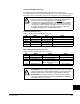
To Enable Torque Proving with an encoder, bit 0 of TorqProve Cnfg (600) must be set
to a “1.” Once this is set, a Type 2 alarm will be active until the following three
parameter settings are entered:
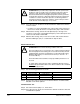
To Enable Encoderless Torque Proving, both bits 0 and 1 of TorqProve Cnfg (600)
must be set to a “1”. Once this is set, a Type 2 alarm will be active until the following
three parameter settings are entered:
Installation/Wiring
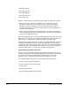
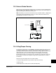
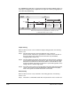
When TorqProve Cnfg is set to “Enable,” the Digital Out 1 relay is used to control the
external brake contactor. The normally open (N.O.) contact, when closed, is intended
to energize the contactor. This provides the mechanical brake with voltage, causing
the brake to release. Any interruption of power to the contactor will set the mechanical
brake. Programming Digital Out1 Sel (380) will be ignored when [TorqProve Cnfg] is
set to “Enable.” See figure 13.2.
Lifting/Torque Proving Application Programming
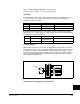
No. Name Value Notes
053 Motor Cntl Sel “4, FVC Vector”
080 Feedback Select “3, Encoder”
412 Motor Fdbk Type “1, Quad Check”
No. Name Value Notes
053 Motor Cntl Sel “4, FVC Vector” or
“0, Sensrls Vect”
080 Feedback Select “1, Slip Comp”
Figure 13.2 – Typical Torque Proving Configuration
24
25
26
27
28
29
30
31
32
Run Fwd
Run Rev
Clear Faults
Float/Micro
Fast Stop
Enable
12
13
115V AC
Brake
Contactor
Brake Set
Normally Open
= Brake Set