
User Manual Instruction Manual

Application Notes
13-7
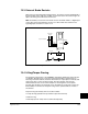
Torque Proving Manual Start Up
It is possible to use the Start Up Routine to tune the motor. However, it is
recommended that the motor be disconnected from the hoist/crane equipment during
the routine. If this is not possible, refer to steps 1 through 12 on the following pages.
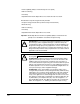
Initial Static Auto Tune Test
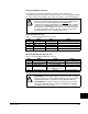
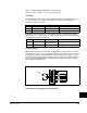
Step 1. Set the following parameters as shown.
Step 2. Press the Start Key on the OIM. Parameters 62-64 will be updated.
Motor Rotation/Encoder Direction Test
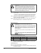
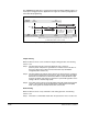
Step 3. Set the following parameters as shown.
!
ATTENTION:To guard against personal injury and/or equipment
damage caused by unexpected brake release, verify the Digital Out 1
brake connections and/or programming. The default
drive
configuration energizes the Digital Out 1 relay when power is applied
to the drive. The GV6000 drive will not control the mechanical brake
until Torque Proving is enabled. If the brake is connected to this relay,
it could be released. If necessary, disconnect the relay output until
wiring/programming can be completed and verified.
No. Name Value Notes
380 Digital Out1 Sel “9, At Speed” keeps brake engaged during test
041-045 Motor NP per nameplate enter motor nameplate data
053 Motor Cntl Sel “4, FVC Vector”
080 Feedback Select “3, Encoder”
061 Autotune “1, Static Tune”
No. Name Value Notes
053 Motor Cntl Sel “0, Sensrls Vect”
080 Feedback Select “0, Open Loop”
090 Digital Out1 Sel “11, Preset Spd1”
238 Fault Config 1 Bit 8, “In PhaseLoss” = 1
Bit 12, “OutPhaseLoss” = 1
380 Digital Out1 Sel “4, Run” releases brake
!
ATTENTION:The following procedure causes motor rotation. To guard
against possible injury and/or equipment damage, ensure that rotation
in either direction will not cause injury and/or equipment damage.
ATTENTION:If the direction of travel is critical at this point, perform
short jogs to determine which run direction (RUNFWD or RUNREV)
should be used in the next steps.