
User Manual Instruction Manual

Application Notes
13-5
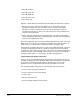
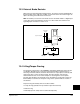
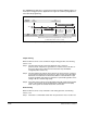
13.3 External Brake Resistor
When using an external dynamic braking resistor, the resistor must be equipped with a
thermostat that opens under the condition of excessive heat in the resistor. Figure 13
depicts the wiring of the DB resistor thermostat.
Note: An auxiliary contact form from the M contactor should be wired to a digital input
on the drive that is programmed to function as a drive enable. See attention note
regarding input contactors in section 4.1.2.
13.4 Lifting/Torque Proving
The Torque Proving feature of the GV6000 is intended for applications where proper
coordination between motor control and a mechanical brake is required. Prior to
releasing a mechanical brake, the drive will check motor output phase continuity and
verify proper motor control (torque proving). The drive will also verify that the
mechanical brake has control of the load prior to releasing drive control (brake
proving). After the drive sets the brake, motor movement is monitored to ensure the
brakes ability to hold the load. Torque Proving can be operated with an encoder or
encoderless.
Torque Proving functionality with an encoder includes:
• Torque Proving (includes flux up and last torque measurement)
• Brake Proving
• Brake Slip (feature slowly lowers load if brake slips/fails)
Figure 13.1 – External Brake Resistor Circuitry
Power On
R (L1)
S (L2)
T (L3)
Power Source DB Resistor Thermostat
Power Off
M
M
(Input Contactor) M
Three-Phase
AC Input
M (AUX)
ENABLE