
User Manual Instruction Manual

2-12
GV6000 AC Drive User Manual
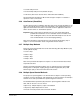
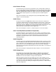
Maximum Voltage
Maximum
Frequency
Base Voltage
(Nameplate)
Base Frequency
(Nameplate)
Run Boost
As an example, consider a 480 volt drive. This drive comes with factory default values
for 480 V, 60 Hz, with motor data defaulted for U.S. motors (HP rated, 1750 RPM, etc.)
By setting the Voltage Class parameter to "low voltage" (this represents 400 V in this
case) the defaults are changed to 400 V, 50 Hz settings with motor data for European
motors (kW rated, 1500 RPM, etc.).
2.3.24 Motor Cable Lengths
The length of cable between the drive and motor may be limited for various application
reasons. The primary areas of concern are:
• Reflected wave
• Cable charging
The reflected wave phenomenon, also known as transmission line effect, produces
very high peak voltages at the motor terminals due to voltage reflection. While
Reliance Electric drives have patented software that limits the voltage peak to 2 times
the DC bus voltage and reduce the number of occurrences, many motors have
inadequate insulation systems to tolerate these peaks.
Caution should be taken to understand the effects and restrictions when applying the
drive to extended motor lead length applications. Proper cable type, motor and drive
selection is required to minimize the potential risks.
2.3.25 Economizer Mode
Economize mode consists of operating the drive in sensorless vector control mode
with an energy saving function (E-SVC). When the drive is in this mode and operating
at steady state output frequency, the output voltage is automatically adjusted as the
load is increased or decreased. This is done so that minimum current is supplied to
the motor thereby optimizing its efficiency. By adjusting the output voltage, the flux
producing current is reduced, but only if the total drive output current does not exceed
75% of motor rated current. In this mode the flux current is not allowed to be less than
50% of the selected flux current parameter value.
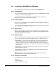
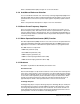
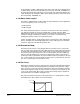
2.3.26 Fan Curve
When Motor Cntl Sel (53) is set to fan/Pump V/Hz, the relationship between frequency
and voltage is shown in the following figure. The fan/pump curve generates voltage
that is a function of the stator frequency squared up to the motor nameplate frequency.
Above base frequency voltage is a linear function of frequency. At low speed, the fan
curve can be offset by Run Boost (70) to provide extra starting torque if needed. No
extra parameters are needed for fan/pump curve.
The pattern matches the speed vs. load characteristics of a centrifugal fan or pump
and optimizes the drive output to those characteristics.