
User Manual Instruction Manual

About the Drive
2-11
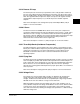
2.3.19 Process PI Loop
The internal process PI function (see parameters 124 to 138) provides closed-loop
process control with proportional and integral control action. The PI function reads a
process variable input to the drive and compares it to a desired setpoint stored in the
drive. The algorithm will then adjust the output of the process PI regulator thereby
changing drive output frequency to try to make the process variable equal the
setpoint.
Refer to the descriptions of PI Configuration (124) and PI Output Meter (138) in
chapter 11 for more information.
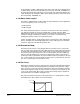
2.3.20 S Curve
The S Curve function of GV6000 drives allows control of the "jerk" component of
acceleration and deceleration through user adjustment of the S Curve % (146). Jerk is
defined as the rate of change of acceleration and/or deceleration. By adjusting the
percentage of S Curve applied to the normal accel/decel ramps, the graph of the ramp
takes the shape of an "S" allowing a smoother transition that produces less
mechanical stress and smoother control for light loads.
Refer to the description of S Curve % (146) in chapter 11 for more information.
2.3.21 Three Skip Bands (Avoidance Frequencies)
The skip band function (see parameters 84 to 87 in chapter 11) provides three skip
bands (also called avoidance frequencies) that the drive will ramp through but will not
continuously run within. You can set the skip frequency (center frequency) and
bandwidth of each band.This function is used to avoid mechanical resonance
operating setpoints.
2.3.22 Flying Start
The flying start feature (enabled in Flying Start En (169)) is used to start into a rotating
motor as rapidly as possible and resume normal operation with a minimal impact on
load or speed. This action will prevent an overcurrent trip and significantly reduce the
time for the motor to reach its desired frequency. Since the motor is "picked up"
smoothly at its rotating speed and ramped to the proper speed, little or no mechanical
stress is present.
Refer to the description of Flying Start En (169) in chapter 11 for more information.
2.3.23 Voltage Class
The voltage class (see parameter 202 in chapter 11) identifies the general input
voltage to the drive. This general voltage includes a range of actual operating
voltages. A 400 volt class drive will have an acceptable input voltage range of 380 to
480 VAC. A 575 volt class will have a range of 475 to 632 volts.
While the hardware remains the same within each class, other variables, such as
factory defaults and power unit ratings, will be different. In most cases, all drives within
a voltage class can be reprogrammed to accommodate a motor within its voltage
class. This can be done by resetting the Voltage Class parameter to a different setup
within the voltage class.