
User Manual Instruction Manual


12-4
GV000 AC Drive User Manual
12.3 Determining Precharge Board Status Using the LED
Indicators (Frames 5 & 6 Only)
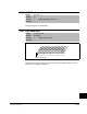
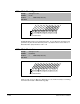
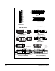
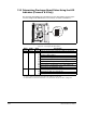
The precharge board LEDs are located above the Line Type jumper shown in figure
12.3. Precharge board LED indicators are found only on frame 5 and 6 drives.
Figure 12.3 – Location of Precharge Status LED (Frame 5 Shown)
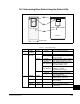
Table 12.2 – Precharge Board LED Indicators
Name Color State Description
Power Green Steady Indicates precharge board power supply is operational.
Alarm Yellow Flashing
Number in “[ ]” indicates flashes and associated alarm
1
.
1
An alarm condition automatically resets when the condition no longer exists.
[1] Low line voltage (<90%).
[2] Very low line voltage (<50%).
[3] Low phase (one phase <80% of line voltage).
[4] Frequency out of range or asymmetry (line sync failed).
[5] Low DC bus voltage (triggers ride-through operation).
[6] Input Frequency momentarily out of range (40-65 Hz).
[7] DC bus short circuit detection active.
Fault Red Flashing
Number in “[ ]” indicates flashes and associated fault
2
.
2
An fault indicates a malfunction that must be corrected and can only be reset after cycling power.
[2] DC bus short (Udc <2% after 20 ms).
[4] Line sync failed or low line (Uac<50% Unom).
Optional
Communications
Module
LINE
TYPE
SPARE 1
SPARE 2
3-PH 1-PH