
User Manual Instruction Manual

2-10
GV6000 AC Drive User Manual
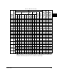
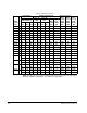
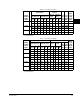
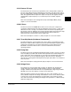
2.3.15 Motor Overload Protection
The motor thermal overload function (enabled in parameter 238) uses an inverse time
(IT) algorithm to model the temperature of the motor. This curve is modeled after a
Class 10 protection thermal overload relay that produces a theoretical trip at 600%
motor current in ten (10) seconds and continuously operates at 100% motor current.
The following parameters are used to set the overload feature:
• Motor NP FLA (42)
• OL Factor (48)
• Motor OL Hertz (47)
• Fault Config 1 (238)
Refer to Motor NP FLA (42) in chapter 11 for more information about this feature.
2.3.16 Shear Pin Fault
This feature allows you to program the drive to fault if the drive output current exceeds
the programmed current limit (see parameter 238). As a default, exceeding the set
current limit is not a fault condition. However, if you want to stop the process in the
event of excess current, the Shear Pin feature can be activated. By programming the
drive Current Lmt Val (148) and enabling the electronic shear pin, the drive will fault if
excess current is demanded by the motor
2.3.17 Drives Peripheral Interface (DPI)
GV6000 drives support Drive Peripheral Interface (DPI) communication protocols for
the primary interface and drive control. The DPI interface is an enhanced serial
communications protocol that provides high functionality and high performance.
The serial DPI connection is used for devices such as Operator Interface Modules
(OIMs), PC interface tool (VS Utilities), and network communication modules.
2.3.18 Network Data Transfer via Datalinks
A Datalink (see parameters 300 to 317) is one of the mechanisms used by GV6000
drives to transfer data to and from a programmable controller via the optional network
interface modules (e.g. DeviceNet or ControlNet). In the case of ControlNet, Datalinks
allow a parameter value to be changed without using an Explicit Message or Block
Transfer.
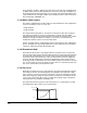
Each Datalink (e.g. A1, A2 for Datalink A) transfers two 16-bit values (A1, A2). If a
32-bit value needs to be transferred, each of the two 16-bit Datalinks must be set to
the same parameter. One Datalink transfers the lower 16 bits; the other, the upper 16
bits.
For example, to set up the drive to receive accel and decel times from the connected
PLC you would make the following parameter settings:
Data In A1 (300) = 140 (the parameter number of Accel Time 1)
Data In A2 (301) = 142 (the parameter number of Decel Time 1)