
User Manual Instruction Manual

2-8
GV6000 AC Drive User Manual
Refer to Feedback Select (80) in chapter 11 for more information.
2.3.9 Auto/Manual Reference Selection
You can override the selected “auto” reference by asserting a digital input (Digital In”x”
Sel (361 to 366)) that has been configured for Manual. This provides a source for local
speed reference control even if a process input signal is the primary speed reference
source.
Refer to the parameter descriptions in chapter 11 for more information.
2.3.10 Seven Preset Frequency Setpoints
There are seven preset frequency parameters (101 to 107) that are used to store a
discrete frequency value. This value can be used for a speed reference or process PI
reference. When used as a speed reference, they are selected via the digital inputs or
the DPI (network) reference command. Refer to the parameter descriptions in chapter
11 for more information.
2.3.11 Motor-Operated Potentiometer (MOP) Function
The Motor-Operated Pot (MOP) function is one of the sources for the speed reference
(selected in Speed Ref A Sel (90) or Speed Ref B Sel (93). The MOP function uses
digital inputs to increment or decrement the speed reference at a programmed rate.
The MOP has these components:
• MOP Rate parameter (195)
• Save MOP Ref parameter (194)
• MOP Frequency parameter (11)
• MOP increment input (parameters 361 to 366)
• MOP decrement input (parameters 361 to 366)
2.3.12 Autotune
Description of parameters determined by the autotune tests.
Flux Current Test
Flux Current Ref (63) is set by the flux current test. Flux current is the reactive portion
of the motor current (portion of the current that is out of phase with the motor voltage)
and is used to magnetize the motor. The flux current test is used to identify the value
of motor flux current required to produce rated motor torque at rated current. When
the flux test is performed, the motor will rotate. The drive accelerates the motor to
approximately two-thirds of base speed and then coasts for several seconds.
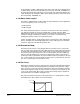
IR Voltage Drop Test
IR Voltage Drop (62) is set by the IR voltage drop test. IR Voltage Drop is used by the
IR Compensation procedure to provide additional voltage at all frequencies to offset
the voltage drop developed across the stator resistance. An accurate calculation of
the IR Voltage Drop will ensure higher starting torque and better performance at low
speed operation. The motor should not rotate during this test.