
User Manual Instruction Manual

2-6
GV6000 AC Drive User Manual
2.3 Overview of GV6000 Drive Features
This section provides an overview of the features in the GV6000 AC Drive.
2.3.1 Analog Inputs
There are two general purpose analog inputs that can be configured either as voltage
(
± 10 VDC) or current (4 -20 mA) inputs.
Each analog input can be configured and scaled independently. Analog Input 1
defaults to current. Analog Input 2 defaults to voltage.
2.3.2 Analog Outputs
There are two general purpose analog outputs that can be configured as voltage (+/-
10 VDC) or current (4-20mA).
Each output can be configured and scaled independently. Analog Output 1 defaults to
current. Analog Output 2 defaults to voltage.
2.3.3 Digital Inputs
There are six general purpose digital inputs. Digital Inputs are configured using the
Digital lnx Sel (361-366) parameters (one for each input). These parameters cannot
be changed while the drive is running.
2.3.4 Digital Outputs
There are three general purpose digital outputs that can be configured to annunciate a
variety of drive operating conditions. The digital outputs are configured as below:
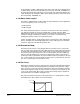
• Digital Output 1 consists of both a normally open contact and a normally closed
contact configured in a Form-C arrangement. The normally closed contact is
connected to terminals 11 and 12, and the normally open contact is connected to
terminals 13 and 12 (Terminal 12 is shared between the normally open and normally
closed contact.).
• Digital Output 2 consists of a normally closed contact. This contact is connected
between terminals 14 and 15.
• Digital Output 3 consists of a normally open contact. This contact is connected
between terminals 16 and 15.
Note: Digital Outputs 2 and 3 are independently programmed and controlled in
software but share a common terminal (terminal 15).
2.3.5 Multiple Control Modes
The GV6000 drive provides a number of user-selectable control modes to suit different
applications:
• Sensorless Vector
• Sensorless Vector Economizer