
User Manual Instruction Manual

11-96
GV6000 AC Drive User Manual
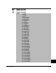
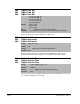
Selects the drive status that will energize an output relay.
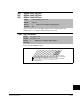
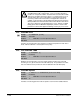
Sets the relay activation level for options 10-15 in Digital Out”x” Sel. Units are
assumed to match the above selection (i.e., At Freq = Hz, At Torque = Amps).
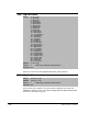
Sets the on delay time for the digital outputs. This is the time between the occurrence
of a condition and activation of the relay.
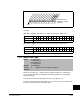
54 = Prof @ Step 13
55 = Prof @ Step 14
56 = Prof @ Step 15
57 = Prof @ Step 16
58 = TB in Manual
Default: 380: 1 = Fault
384: 4 = Run
388: 4 = Run
Access: 1 Path: Inputs & Outputs>Digital Outputs
See also: 1-4, 12, 48, 53, 137, 147, 157, 184, 218, 381-383, 385, 386, 390
380
384
388
Digital Out1 Sel
Digital Out2 Sel
Digital Out3 Sel
381
385
389
Digital Out1 Level
Digital Out2 Level
Digital Out3 Level
Range: 0.0 to 819.2 [0.1]
Default: 0.0
Access: 1 Path: Inputs & Outputs>Digital Outputs
See also: 380
382
386
390
Digital Out1 OnTime
Digital Out2 OnTime
Digital Out3 OnTime
Range: 0.00 to 600.00 sec [0.1 sec]
Default: 0.00 sec
Access: 2 Path: Inputs & Outputs>Digital Outputs
See also: 380