
User Manual Instruction Manual


11-82
GV6000 AC Drive User Manual
Selects whether the signed value or absolute value of a parameter is used before
being scaled to drive the analog output.
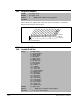
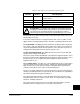
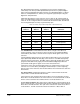
341 Anlg Out Absolut
Range: See figure 11.33
Default: See figure 11.33
Access: 2 Path: Inputs & Outputs>Analog Outputs
See also:
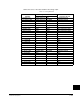
Figure 11.33 – Anlg Out Absolute (341)
1
xx
1
xxxxxxxxxxxx
10 01234567891112131415
1
=Absolute
0
=Signed
x = Reserved
Bit #
Factory Default Bit Values
Analog Out1
Analog Out2
342
345
Analog Out1Sel
Analog Out2 Sel
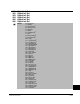
Range: 0 = Output Freq
1 = Command Freq
2 = Output Amps
3 = Torque Amps
4 = Flux Amps
5 = Output Power
6 = Output Volts
7 = DC Bus Volts
8 = PI Reference
9 = PI Feedback
10 = PI Error
11 = PI Output
12 = %Motor OL
13 = %Drive OL
14 = CommandedTrq
15 = MtrTqrCurRef
16 = Speed Ref
17 = Speed Fdbk
18 = Pulse ln Ref
19 = Torque Est
20 = Scale Block 1
21 = Scale Block 2
22 = Scale Block 3
23 = Scale Block 4
24 = Param Cntl
25 = SpdFb NoFilt
Default: 0 = Output Freq
Access: 1 Path: Inputs & Outputs>Analog Outputs
See also: 1 - 7, 12, 135 - 138, 219, 220