
User Manual Instruction Manual

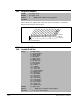

Parameter Descriptions
11-81
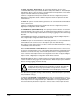
Selects drive response when an analog signal loss is detected. Signal loss is defined
as an analog signal less than 1 V or 2 mA. The signal loss event ends and normal
operation resumes when the input signal level meets or exceeds 1.5 V or 3 mA.
One of the selections (1=Fault) stops the drive on signal loss. All other choices make it
possible for the input signal to return to a usable level while the drive is still running.
Selects the mode for analog outputs.
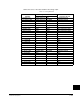
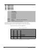
327 Analog In 2 Loss
Range: 0 = Disabled
1 = Fault
2 = Hold Input (use last frequency command)
3 = Set Input Lo (use Minimum Speed as frequency command)
4 = Set Input Hi (use Maximum Speed as frequency command)
5 = Go to Preset1 (use Preset1 as frequency command)
6 = Hold OutFreq (maintain last output frequency)
Default: 0 = Disabled
Access: 2 Path: Inputs & Outputs>Analog Inputs
See also: 91, 92
!
ATTENTION:Setting parameter 327 to a value greater than 1 allows the
input signal to return to a usable level while the drive is running. If a lost
analog signal is restored while the drive is running, the drive will ramp to
the restored reference level at the rate specified in Accel Time 1 (140),
Accel Time 2 (141), Decel Time 1 (142), and Decel Time 2 (143). Be
aware that an abrupt speed change may occur depending upon the new
reference level and the rate specified in these parameters. Failure to
observe this precaution could result in bodily injury.
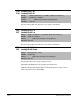
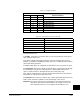
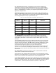
340 Analog Out Config
Range: See figure 10.32
Default: See figure 10.32
Access: 0 Path: Inputs & Outputs>Analog Outputs
See also:
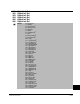
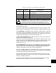
Figure 11.32 – Analog Out Config
1
xx
1
xxxxxxxxxxxx
10 01234567891112131415
1
=Current
0
=Voltage
x = Reserved
Bit #
Factory Default Bit Values
Analog Out1
Analog Out2