
User Manual Instruction Manual

11-78
GV6000 AC Drive User Manual
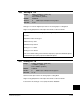
Selects the type of input signal being used for analog input 1 and 2. These inputs can
be configured as 10VDC (unipolar or bipolar) or as 4-20mA inputs. See scaling
parameters Analog ln 1 (322 and 323) and Analog ln 2 (325 and 326).
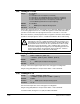
Enables/disables the square root function for each analog input.
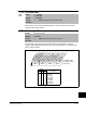
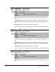
320 Anlg In Config
Range: See figure 11.30
Default: See figure 11.30
Access: 0 Path: Inputs & Outputs>Analog Inputs
See also: 322, 323, 325, 326
Figure 11.30 – Anlg ln Config (320)
1
xx
1
xxxxxxxxxxxx
10 01234567891112131415
1
=Current
0
=Voltage
x =Reserved
Bit #
Factory Default Bit Values
Analog In1
Analog In2
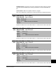
Analog ln 1 Bit Term
0 to 10 VDC or
-10 to +10 VDC
Bit 0 = 0 1, 2 (17 to 18 not jumpered)
4 to 20 mA Bit 0 = 1 1, 2 (17 to 18 jumpered)
Analog ln 2 Bit Term
-0 to 10 VDC or
-10 to +10 VDC
Bit 1 = 0 3, 4 (19 to 20 not jumpered)
4 to 20 mA Bit 1 = 1 3, 4 (19 to 20 jumpered)
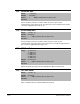
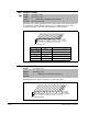
321 Anlg In Sqr Root
Range: See figure 11.31
Default: See figure 11.31
Access: 2 Path: Inputs & Outputs>Analog Inputs
See also:
Figure 11.31 – Anlg in Sqr Root (321)
1
xx
1
xxxxxxxxxxxx
10 01234567891112131415
1
=Current
0
=Voltage
x = Reserved
Bit #
Factory Default Bit Values
Analog Out1
Analog Out2