
User Manual Instruction Manual

11-66
GV6000 AC Drive User Manual
Captures and displays Drive Alarm 1 at the time of the last fault.
Captures and displays Drive Alarm 2 bit pattern at the time of last fault.
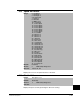
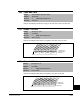
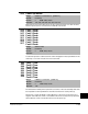
229 Alarm 1 @ Fault
Range: See figure 11.22
Default: Read Only
Access: 1 Path: Utility>Diagnostics
See also: 211, 224-230
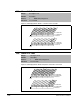
Figure 11.22 – Alarm 1 @ Fault (229)
000000
x
000000000
10 01234567891112131415
1
=Condition True
0
=Condition False
x =Reserved
Bit #
Prechrg Actv
UnderVoltage
Power Loss
Str At PwrUp
Anlg in Loss
IntDBRes OH
Drv OL Lvl 1
Drv OL Lvl 2
Decel Inhibt
Waking
Motor Therm
In PhaseLoss
Load Loss
Ground Warn
Brk Slipped
00
xxxxxxxxxxxxx
26 161718192021222324252728293031
1
=Condition True
0
=Condition False
x =Reserved
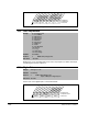
Bit #
Prof SetHome
PTC HW
Reserved
x
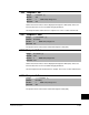
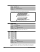
230 Alarm 2 @ Fault
Range: See figure 11.23
Default: Read Only
Access: 1 Path: Utility>Diagnostics
See also: 211, 221-230
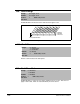
Figure 11.23 – Alarm 2 @ Fault (230)
0000000000000000
10 01234567891112131415
1
=Condition True
0
=Condition False
x = Reserved
Bit #
DigIn CflctA
DigIn CflctB
DigIn CflctC
Bipolr Cflct
MtrTyp Cflct
NP Hz Cflct
MaxFrq Cflct
VHz NegSlope
IR Vlts Rang
FlxAmps Rang
SpdRef Cflct
Ixo Vlt Rang
Sleep Config
TB Ref Cflct
PTC Conflict
Brk Slipped
xxx
0
xxxxxxxxxxxx
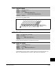
26 161718192021222324252728293031
1
=Condition True
0
=Condition False
x = Reserved
Bit #
TrqPrv Cflct
ProfStpCflct
UserSetCflct
PICfgCflct