
User Manual Instruction Manual


11-50
GV6000 AC Drive User Manual
Sets the time that the drive will remain in power loss mode before a fault is issued.
When set to a non-zero value, selects the change in level at which the Power Loss will
occur.
The drive can use the percentages referenced in Power Loss Mode (184) or a trigger
point can be set for the line loss detection as follows:
V
Trigger
= [DC Bus Memory] - [Power Loss Level]
A digital input (programmed to 29 = Pwr Loss Lvl) is used to toggle between fixed
percentages and the detection level.
Sets the percentage of motor nameplate torque at which a load loss alarm will occur.
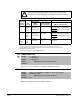
185 Power Loss Timer
Range: 0.0 to 60.0 sec [0.1 sec]
Default: 0.5 sec
Access: 1 Path: Dynamic Control>Power Loss
See also: 184
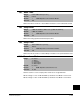
186 Power Loss Level
Range: 0.0 to 999.9 [0.1 VDC]
Default: Drive Rated Volts
Access: 1 Path: Dynamic Control>Power Loss
See also:
!
ATTENTION: If the value for Power Loss Level (186) is greater than
18% of DC Bus Memory (13), the user must provide a minimum line
impedance to limit inrush current when the power line recovers. The
input impedance should be equal to or greater than the equivalent of a
5% transformer with a VA rating 5 times the drive input VA rating. Failure
to observe this precaution could result in damage to equipment.
187 Load Loss Level
Range: 0.0 to 800.0% [0.1%]
Default: 200.0%
Access: 2 Path: Dynamic Control>Power Loss
See also: 211, 259