
User Manual Instruction Manual


Contents
IX
List of Tables
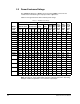
Table 2.1 – 240 VAC Power Ratings ........................................................................ 2-2
Table 2.2 – 480 VAC Power Ratings ........................................................................ 2-3
Table 2.3 – 600 VAC Power Ratings ........................................................................ 2-4
Table 2.4 – 325 VDC Power Ratings........................................................................ 2-5
Table 2.5 – 650 VDC Power Ratings........................................................................ 2-5
Table 2.6 – GV6000 AC Drive EN1800-3 EMC Compatibility ................................ 2-16
Table 2.7 – Power Terminal Block Locations Table ............................................... 2-18
Table 2.8 – I/O Cassette and Terminal Block Locations......................................... 2-19
Table 2.9 – Removing the I/O Control Cassette ..................................................... 2-19
Table 2.10 – Drive Connection Descriptions .......................................................... 2-20
Table 2.11 – Standard Communication Kits and Options....................................... 2-21
Table 2.12 – Operator Interface Options ................................................................ 2-21
Table 2.13 – Regulator and Encoder Board Option Kits......................................... 2-21
Table 2.14 – PC-Based Utility Model Number and Instruction Manual Number..... 2-22
Table 3.1 – Fan VA Ratings (DC Input Only)............................................................ 3-5
Table 4.1 – Recommended Shielded Wire ............................................................... 4-2
Table 4.2 – Recommended Signal and Control Wire ............................................... 4-5
Table 4.3 – Control Terminal Block Specifications ................................................... 4-5
Table 4.4 – AC Line Input Fuse Selection Values (240 VAC) ................................ 4-10
Table 4.5 – AC Line Input Fuse Selection Values (480 VAC) ................................ 4-11
Table 4.6 – AC Line Input Fuse Selection Values (600 VAC) ................................ 4-12
Table 4.7 – DC Common Bus Input Fuse Selection Values ................................... 4-13
Table 5.1 – Power Wiring Access Panel Removal ................................................... 5-2
Table 5.2 – Power Terminal Block Specifications..................................................... 5-3
Table 5.3 – Power Terminal Descriptions................................................................. 5-7
Table 5.4 – Braking Resistor Capacity ..................................................................... 5-9
Table 6.1 – Wiring Signal and Control I/O to the Terminal Block ............................. 6-2
Table 6.2 – Wiring Encoder Terminal Block ............................................................. 6-4
Table 6.3 – Parameter Configuration for Figure 6.2 Wiring Example ..................... 6-11
Table 8.1 – How to Adjust Each Parameter Type..................................................... 8-7
Table 11.1 – Default Values for Preset Speeds 1-7 ............................................. 11-26
Table 11.2 – Conditions Required to Start Drive when Sleep-Wake is Enabled 11-48
Table 11.3 – Analog Out1/2 Sel............................................................................ 11-83
Table 11.4 – Speed Select Inputs......................................................................... 11-86
Table 11.5 – Spd/Trq Sel # Inputs........................................................................ 11-87
Table 11.6 – Default Values for Parameters 361-366 .......................................... 11-87
Table 11.7 – Drive Response to Jog Forward and Jog Reverse Inputs ............... 11-89
Table 11.8 – Effect of Speed Select Input State on Selected Reference ............. 11-90
Table 12.1 – Status LED Definitions....................................................................... 12-3
Table 12.2 – Precharge Board LED Indicators ....................................................... 12-4
Table 12.3 – Types of Alarms................................................................................. 12-5
Table 12.4 – Alarm Descriptions............................................................................. 12-6
Table 12.5 – Alarm Names Cross-Referenced by Alarm Numbers ........................ 12-9
Table 12.6 – Fault Types ...................................................................................... 12-10
Table 12.7 – Fault Descriptions and Corrective Actions....................................... 12-12
Table 12.8 – Fault Names Cross-Referenced by Fault Number........................... 12-17
Table 12.9 – Test Point Codes and Functions...................................................... 12-18
Table 12.10 – Drive Does Not Start From Start, Run,
or Jog Inputs Wired to the Terminal Block.................................. 12-19
Table 12.11 – Drive Does Not Start or Jog From OIM.......................................... 12-20
Table 12.12 – Drive Does Not Respond to Changes in Speed Command........... 12-20
Table 12.13 – Motor and/or Drive Will Not Accelerate to Commanded Speed..... 12-21
Table 12.14 – Motor Operation is Unstable.......................................................... 12-22