GV3000/SE Operator Interface Module (OIM) User Guide Version 2.
The information in this manual is subject to change without notice. Throughout this manual, the following notes are used to alert you to safety considerations: ! ATTENTION: Identifies information about practices or circumstances that can lead to personal injury or death, property damage, or economic loss. Important: Identifies information that is critical for successful application and understanding of the product.
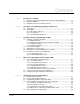
CONTENTS Contents Chapter 1 Introduction to the OIM 1.1 Differences Between the OIM and the Front Panel Keypad/Display ............... 1-1 1.2 Related Publications ........................................................................................ 1-2 1.3 Getting Assistance from Reliance Electric....................................................... 1-3 Chapter 2 Description of the OIM Keypad, Display, and Indicators 2.1 The Keypad .................................................................
Chapter 6 Using the OIM to Monitor and Control the Drive 6.1 Using the OIM to Monitor Drive Outputs ..........................................................6-1 6.1.1 Description of the Monitor Mode Outputs ..............................................6-1 6.1.2 Selecting the Outputs to Monitor ...........................................................6-2 6.1.3 Using Help in Monitor Mode ..................................................................6-3 6.1.
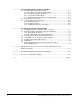
List of Figures Figure 2.1 – OIM Keypad, Display, and Indicators ................................................... 2-1 Figure 2.2 – OIM Display in Program Mode with Main Menu Displayed .................. 2-5 Figure 3.1 – Enclosure Cutout Dimensions .............................................................. 3-3 Figure 3.2 – OIM Power-Up Sequence..................................................................... 3-5 Figure 3.3 – Contrast Adjustment Screen...............................................
IV GV3000/SE Operator Interface Module (OIM) User Guide, Version 2.
List of Tables Table 2.1 – Programming Key Descriptions ............................................................ 2-2 Table 2.2 – Control Key Descriptions ...................................................................... 2-3 Table 2.3 – Drive Status Indicators .......................................................................... 2-5 Table 2.4 – Key Indicators ....................................................................................... 2-6 Table 2.5 – Special Display Characters.......
VI GV3000/SE Operator Interface Module (OIM) User Guide, Version 2.
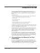
CHAPTER 1 Introduction to the OIM The Operator Interface Module (OIM) is a keypad and display that connects to Reliance GV3000/SE™ drives. It is compatible with version 6.0 and older versions of the GV3000/SE drive software. The OIM communicates serially to the Regulator board.
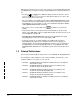
Although most functions are the same, some functions are performed differently with the OIM than they are with the front panel keypad/display. Some important differences are: • Pressing or on the OIM immediately starts the motor if the control source is set to OIM. Make sure the motor and driven machinery are safe to start before pressing either of these keys. • For V/Hz regulation, the identification procedure (IDENTIFICATION RQST, H.020) cannot be performed using the OIM.
For parameter descriptions, fault information, and troubleshooting procedures, see the software I/M that corresponds to your system: 1.
1-4 GV3000/SE Operator Interface Module (OIM) User Guide, Version 2.
CHAPTER 2 Description of the OIM Keypad, Display, and Indicators This chapter describes how to use the keypad, display, and indicators on the OIM to program, monitor, and control the drive. Figure 2.1 shows the OIM in program mode with keys, indicators, and screen information called out. Figure 2.1 – OIM Keypad, Display, and Indicators 2.1 The Keypad The OIM keys are grouped by programming and control functions, as shown in figure 2.1.
Table 2.1 – Programming Key Descriptions Key Mode Function Program or Monitor Cycles between program and the three monitor mode screens. If you switch back to program mode, you are returned to the menu or parameter entry screen you were in before going to monitor mode. In fault, alarm, or diagnostics menus, returns you to the screen you were in before pressing Program or Monitor .
Table 2.1 – Programming Key Descriptions (Continued) Key Mode Program Function Move the cursor between menu items or between the parameters and options in the menus. After you select a parameter to change, these keys increase or decrease the digit at the cursor, or move between items in a list. Hold down one of these keys to change values more quickly. See chapter 4 for more information on changing values. In help screens and fault messages, these keys move to more text if it is available.
Table 2.2 – Control Key Descriptions (Continued) Key Mode Function Program or Monitor ! ATTENTION: Pressing on the OIM immediately starts the motor if the control source is set to OIM. Make sure the motor and driven machinery are safe to start before pressing this key. Failure to observe this precaution could result in severe bodily injury or loss of life. When the control source is set to OIM, jogs the motor when held down (and the drive is ready). The motor ramp stops when it is released.
2.2 The Display OIM screens allow you to program and monitor the drive. Figure 2.2 shows the OIM display at the Main Menu in program mode. Figure 2.2 – OIM Display in Program Mode with Main Menu Displayed The display contains three main areas: • the normal display area, where the program or monitor mode information is displayed. See chapter 4 for information on program mode. See chapter 6 for information on monitor mode. • the status indicator area. See section 2.2.1 for more information.
Table 2.3 – Drive Status Indicators (Continued) Indicator State Description Interlock OK On The terminal strip function loss input is closed. See the hardware I/M for more information. Also see the description of Function Loss Response (P.026) in the software I/M for a description of the types of responses available on function loss. Off The terminal strip function loss input is open. See the hardware I/M for more information. On The drive is ready to run or jog.
Table 2.4 – Key Indicators (Continued) Key Indication AUTO Description The drive is receiving the reference from the terminal strip input or network option. MANUAL The drive is receiving the reference set by the front panel keypad/display or the OIM. FORWARD The drive is set to run the motor in the forward direction. Blinks when forward is selected but the drive is not yet running forward. REVERSE The drive is set to run in the motor in the reverse direction.
2-8 GV3000/SE Operator Interface Module (OIM) User Guide, Version 2.
CHAPTER 3 Installing, Powering, and Adjusting the OIM This chapter tells you how to install the OIM, what to expect on power up, and how to make adjustments you might need for your application. 3.1 Installing or Replacing the OIM Installation consists of mounting the OIM and connecting it to the GV3000/SE drive. Replacing the OIM consists of removing the old OIM and installing a new one. Note that the OIM is connected to the RS-232 serial port on the GV3000/SE Regulator board.
3.1.2 Equipment Needed to Install or Replace the OIM To install or replace the OIM, you will need: • OIM kit (M/N 2RK3000) • Drill with 5.0 mm drill bit • #1 Phillips-head screwdriver • Strain relief for serial cable 3.1.3 Installing the OIM To install the OIM: Step 1. Disconnect power from the drive. ! ATTENTION: Do not install or remove modification kits with power applied to the drive. Disconnect and lock out incoming power before attempting such installation or removal.
Figure 3.1 – Enclosure Cutout Dimensions Step 4. Deburr the drilled holes and cutout. Step 5. Remove the backing from the gasket. Place the gasket around the cutout on the inside of the enclosure door. Step 6. Place the OIM on the gasket and align the mounting holes. Step 7. Place the bezel around the cutout on the outside of the enclosure hole and align the mounting holes. Step 8. Secure the bezel and the OIM to the enclosure door using the hardware included in the kit. Step 9.
Step 11. Open the hatch labeled COM PORT ACCESS on the front cover of the GV3000/SE drive. (For Bookshelf drives, you will need to remove the breakout panel above the RS-232 connector.) Plug the serial cable into the 10-pin serial port connector. Make sure it locks into place. You can now power up the drive, which will power the OIM. See section 3.2 for more information on OIM power up. 3.1.4 Replacing the OIM ! ATTENTION: Do not install or remove modification kits with power applied to the drive.
Figure 3.2 – OIM Power-Up Sequence When the power-up sequence is complete, the OIM enters either program mode or monitor mode, depending on the mode the drive was in at power down. Any faults or alarms that are detected during power up are displayed before you see the normal displays. See chapter 7 of this manual for information on alarms and faults. See the GV3000/SE hardware I/M for instructions on powering up the drive. 3.
Figure 3.3 – Contrast Adjustment Screen Step 2. Use to increase the contrast (make the screen darker) or the contrast (make the screen lighter). Step 3. Press screen. 3.4 to decrease to save the new contrast setting and return to the previous Changing the Language Displayed on the OIM The OIM can display text in English, German, French, Spanish, or Italian. The default language is English. You can change the language at any time except when you are in a parameter entry screen or during self-tuning.
3.5 Scaling Speed Units for Your Application You can scale the speed units to match your application’s requirements. Scaled speed units are used on the OIM display only. If vector regulation is selected, you can scale speed units for RPM, % of MOTOR TOP SPEED (U.017), or your own units. If V/Hz regulation is selected, you can scale speed units for HERTZ, % of MOTOR NAMEPL BASE FRQ (H.001), or your own units.
Step 3. Move the cursor to Define Speed Units. Press . The Define Speed Units screen is displayed, as shown in figure 3.5. The currently selected units are shown on the right side of the screen. Figure 3.5 – Define Speed Units Screen - Vector Regulation Step 4. Move the cursor to the units of measure that you want. Press . If you selected RPM (Vector), HERTZ (V/Hz), or % (Both): The units are changed and you are returned to the previous screen If you selected OTHER: See section 3.5.2. 3.5.
Step 1. In this screen, you define the units of measure that will be used on the display. The tag can be up to six characters long. To create the tag: • Press or to scroll through the characters until the character you want is displayed. • Press to move to the next character. Select the next character. • Repeat this procedure until the tag is complete. Step 2. Press when the tag is correct. The full scale value screen is displayed, as shown in figure 3.7. Figure 3.
Using the example of a full scale value of 500.0 and MOTOR TOP SPEED of 1750, the OIM would convert the speed units as follows: Actual Speed (RPM) Conversion Displayed Value (ft/min) 1750 1750 * 500.0 1750 500.0 875 875 * 500.0 1750 250.0 -350 -350 * 500.0 1750 -100.0 0 0 * 500.0 1750 0.0 Note that normalized values in the drive remain at 1 count in 4095 regardless of the full scale value setting. Step 4.
CHAPTER 4 Basics of Programming the Drive Using the OIM ! ATTENTION: Only qualified electrical personnel familiar with the construction and operation of this equipment and the hazards involved should install, adjust, operate, and/or service this equipment. Read and understand this section in its entirety before proceeding. Failure to observe this precaution could result in severe bodily injury or loss of life.
Figure 4.1 – Main Menu Screen To view the rest of the menu, press . The full Main Menu includes: • Quick Start • Speed Control • Application Setup • Performance Tuning • Motor Data • Drive Status • Regulator Terminal Strip • Option Port Configuration • Memory Functions • Additional Parameters Menus contain other menus and parameters. To select an item in a menu, press item. Press or until the cursor ( ) is pointed at the . The menu or parameters in that menu item are displayed. 4.1.
The Main Menu help screen is shown in figure 4.2. Figure 4.2 – Main Menu Help Screen In a menu, help gives an overview of the options available in the menu. An example of the Speed Control menu help is shown in figure 4.3. Figure 4.3 – Example of the Speed Control Menu Help Screen In a parameter entry screen, the help screen gives you the parameter name, number, type, and units of measure of the parameter. An example of a parameter help screen is shown in figure 4.4. Figure 4.
• The parameter type is INPUT. This means you can change the value. • The save type is RETENTIVE. This means the parameter is saved through a power cycle. • The units of measure are RPM. If units of measure do not apply, this line is blank. For full descriptions of parameters, see the software I/M. 4.1.3 Accessing the Parameters Parameters are accessed through the menus. The menu paths to get to parameters are listed in Appendix B.
Step 2. Press . The Speed Control Menu is displayed, as shown in figure 4.6. 6SHHG &RQWURO 'HILQH 6SHHG 8QLWV 6SHHG /LPLWV $FFHO 'HFHO 7LPHV )25:$5' 5(9 &21),*85( ) 5 (1$%/(' Figure 4.6 – Speed Control Menu Step 3. Use to move the cursor until it points to Jog Configure, as shown in figure 4.7. 6SHHG &RQWURO )25:$5' 5(9 &21),*85( 'UDZ 7ULP &RQILJXUH 6 &859( (1$%/( -RJ &RQILJXUH ) 5 (1$%/(' 2)) Figure 4.7 – Speed Control Menu with Cursor at Jog Configure Step 4. Press .
4.1.4 Viewing Parameter Values In the parameter lists, parameter values are shown to the right of the parameter name, as shown in figure 4.8. After you have looked at the parameter values, press return to the previous menu. to Note that read-only (output) parameter values are updated from the drive approximately two times per second. 4.1.
. Figure 4.10 – Parameter Entry Screen with a List of Options Step 4. If the existing value is shown, go to step 5. If you see a list of options: a. Move the cursor to the option you want to select. b. Press to accept the option. c. Go to step 6. Step 5. If you see the existing value: a. Use and to move the cursor ( needs to change. b. Press numbers: or ) to the digit or sign (+ or -) that to change the number or sign.
4.1.6 Parameter Values that Cannot be Changed In some cases, you cannot change parameter values. If this is the case, an error message is displayed when you try to select it. The situations in which you cannot change parameter values are: • When the drive is running and the parameter you are changing is configurable. Configurable parameters cannot be changed while the drive is running or jogging. Stop the drive to change the parameter. • When programming protection is enabled. See section 4.
Step 3. Select the Memory Functions menu. Step 4. Select the PROGRAMMING DISABLE (P.051) parameter. If programming is currently: • Disabled: The message ”Do you wish to enter the password to ENABLE program protection?” is displayed. • Enabled: The message “Do you wish to enter the password to DISABLE program protection?” is displayed. Step 5. Select YES or NO. Press . • YES: Advances you to the PROGRAMMING DISABLE parameter entry screen, as shown in figure 4.11. • NO: Keeps the current setting.
Step 4. Select ON. Press . The defaults are restored and you are returned to the Memory Functions menu. The restore defaults operation is complete. After restoring the factory defaults, perform the Quick Start procedure described in chapter 5. 4-10 GV3000/SE Operator Interface Module (OIM) User Guide, Version 2.
CHAPTER 5 Using Quick Start to Program the Drive ! ATTENTION: Only qualified electrical personnel familiar with the construction and operation of this equipment and the hazards involved should install, adjust, operate, and/or service this equipment. Read and understand this chapter in its entirety before proceeding. Failure to observe this precaution could result in severe bodily injury or loss of life.
5.2 Using the Quick Start Exit Menu Quick Start automates the process of entering the values for selected parameters by taking you to the next Quick Start parameter when a parameter value is accepted. If you want to go back to a previous parameter or exit Quick Start before the process is complete, press . The Quick Start exit menu is displayed, as shown in figure 5.1. Figure 5.1 – Quick Start Exit Menu The exit options are: • Return to previous step: Goes back to the previous parameter.
5.3 Programming the Drive Using Quick Start ! ATTENTION: Only qualified electrical personnel familiar with the construction and operation of this equipment and the hazards involved should install, adjust, operate, and/or service this equipment. Read and understand this chapter in its entirety before proceeding. Failure to observe this precaution could result in severe bodily injury or loss of life.
Step 7. After CURRENT LIMIT (P.005), what happens next depends on the regulation type. If you selected: • V/Hz Regulation: Quick Start is complete and you are returned to the Main Menu. • Vector Regulation: The self-tuning screen is displayed, as shown in figure 5.3. Go to step 8. Figure 5.3 – Quick Start Self-Tuning Screen - Vector Regulation Step 8. If you want the drive to self-tune, select YES. See section 5.4 for information about self-tuning.
ATTENTION: The motor will rotate during self-tuning. Stay clear of rotating machinery. Failure to observe this precaution could result in bodily injury. ! ATTENTION: The motor must be uncoupled from the driven load during self-tuning. If the motor is not uncoupled, incorrect parameter values will result. The motor must also be uncoupled from any shaft-coupled devices, such as reducers, belts, and brakes. Failure to observe this precaution could result in damage to, or destruction of, the equipment.
Figure 5.4 – Attention Screen Displayed After Enabling Self-Tuning Step 3. Press to clear the screen and continue. The screen shown in figure 5.5 is displayed. Figure 5.5 – Self-Tuning Enabled Screen Step 4. Press to start self-tuning. A message and the motor speed during self-tuning are displayed, as shown in figure 5.6. In the few minutes that self-tuning takes, you can view other outputs by going to monitor mode. Figure 5.
Step 5. When self-tuning is complete, the OIM displays one of these messages: • Self Tuning has updated the gains: Self-tuning was successfully completed. • Emergency stop or fault stop occurred during self-tuning. Self-tuning aborted: The self-tuning was not completed because of a fault or because was pressed. See TORQUE SELF-TUNE RSLT, U.009 (in the Self Tuning Parameters menu), and the software I/M for descriptions of the possible results. Repeat self-tuning when the problem is corrected. Step 6.
5.5 Quick Start Parameter Descriptions Brief descriptions of the Quick Start parameters are provided here for your reference. Full descriptions of the parameters are provided in the software I/M. These descriptions are listed in the order that they are displayed during the Quick Start procedure for vector-regulated drives. For V/Hz regulated drives, fewer parameters are displayed and the order is slightly different.
ENCODER PPR (U.001) Selects the number of pulses per revolution (PPR) of the encoder being used or selects sensorless vector control (SVC) if no encoder is used. Parameter Range: 512,1024, 2048, 4096 PPR, SENSORLESS Default Setting: 1024 PPR Parameter Type: Configurable If SENSORLESS is not selected, the value of this parameter is automatically set if torque control self-tuning is performed successfully. ! ATTENTION: The setting of parameters U.001 (Encoder PPR), U.002 (Motor Poles), U.
MOTOR NAMEPL BASE FRQ (H.001 or U.003) In vector regulation, this parameter identifies the motor base frequency as it appears on the motor nameplate. Parameter Range: 15.0 to 240.0 HERTZ (vector) 30.0 to 200.0 HERTZ (V/Hz) Default Setting: 60.0 HERTZ Parameter Type: Configurable ! ATTENTION: The setting of parameters U.001 (Encoder PPR), U.002 (Motor Poles), U.003 (Motor Nameplate Base Frequency), and U.005 (Motor Nameplate RPM) determins the motor manximum speed.
MOTOR NAMEPL VOLTS (H.000 or U.007) Identifies the motor rated (nominal) voltage as it appears on the motor nameplate. Parameter Range: 100 to 690 VOLTS Default Setting: 460 VOLTS Parameter Type: Configurable MOTOR NAMEPL AMPS (H.002 or U.004) Identifies the motor rated amps as it appears on the motor nameplate. Parameter Range: Power Module-dependent. See the software I/M for more information. Default Setting: Power Module-dependent. See the software I/M for more information.
DECEL TIME (P.002) Specifies the time it takes for the motor speed to decrease to zero speed from MAXIMUM SPEED, P.004 (V/Hz regulation) or MOTOR TOP SPEED, U.017 (vector regulation). Parameter Range: 1.0 to 999.9 SEC (V/Hz) 0.1 to 999.9 SEC (vector) Default Setting: 20.0 SEC Parameter Type: TUNABLE The time the motor takes to decrease speed (except during a coast-to-rest stop) is directly proportional to the value in this parameter. This parameter does not apply to jog.
MAXIMUM SPEED (P.004) Limits the reference. Regardless of the supplied reference, the regulator will not command a speed greater than the value programmed for this parameter. Parameter Range: 15.0 to OVERFREQUENCY LIMIT (H.022) HERTZ (V/Hz) 10 to MOTOR TOP SPEED (U.017) RPM (vector) Default Setting: 60.
MAGNET CURRENT PRCNT (U.006) Identifies the percentage of magnetizing current (no-load amps) with respect to motor rated amps. Parameter Range: 10.0 to 80.0% Default Setting: Power Module-dependent. See the software I/M for more information. Parameter Type: Configurable ! ATTENTION: If this parameter is set incorrectly, overcurrent or excessive heating of the motor could result. Failure to observe this precaution could result in damage to, or destruction of, the equipment.
CHAPTER 6 Using the OIM to Monitor and Control the Drive The OIM allows you to monitor the outputs to the motor, such as speed, voltage, amperage, and power. You can choose one of several viewing options. The OIM also allows you to control the motor. Motor control options available through the OIM include starting, stopping, jogging, and setting the manual reference and control source. 6.1 Using the OIM to Monitor Drive Outputs You can monitor up to six drive outputs when the OIM is in monitor mode.
• Output power: Output power of the drive in kilowatts. This is intended for display purposes as a general indication of output power in kilowatts. • Reference: The speed or torque the drive attempts to reach when the drive is running. The reference will be Manual or Auto if the drive is regulating speed, or Torque Reference if the drive is regulating torque. 6.1.2 Selecting the Outputs to Monitor You can view one of three monitor mode screens.
Step 4. To go to program mode, press again. As you press , you will cycle between program mode and the three monitor mode screens. 6.1.3 Using Help in Monitor Mode Pressing in monitor mode displays the labels for the drive status indicators in the selected language. To return to monitor mode, press . 6.1.4 Changing the Manual Reference Using the OIM The reference is displayed on the six- and four-output monitor mode screens.
6.2 Selecting the Control Source Use to select the control source for the drive. The control source can be set to one of four options: • LOCAL: The drive’s front panel keypad/display is used to control the drive. • TERMBLK: The signals at the Regulator board terminal strip control the drive. • OPTION: An option board, such as the AutoMax Communication Network board, controls the drive. • OIM: The OIM keys control the drive. To select the control source: Step 1. Stop the drive if it is running. Step 2.
6.3 Using the OIM to Control the Drive When the control source is set to OIM, the OIM can be used to control the drive. ! ATTENTION: Pressing or on the OIM immediately starts the motor if the control source is set to OIM. Make sure the motor and driven machinery are safe to start before pressing either of these keys. Failure to observe this precaution could result in severe bodily injury or loss of life. 6.3.
CHAPTER 7 Troubleshooting the Drive Using the OIM ! ATTENTION: Only qualified electrical personnel familiar with the construction and operation of this equipment and the hazards involved should install, operate, and/or service this equipment. Read and understand this section in its entirety before proceeding. Failure to observe this precaution could result in severe bodily injury or loss of life. Using the OIM, you can troubleshoot drive problems using one of several methods.
The fault screen tells you which fault occurred - in this example, the HIGH LINE VOLTAGE fault. If more faults occur, they are displayed after the first fault. is pressed to clear When an alarm occurs: • the alarm or fault indicator turns on. • alarms are not logged. • an alarm message is displayed on the OIM screen, such as the one shown in figure 7.2. Figure 7.2 – Example of an Alarm Screen The alarm message screen tells you which alarm occurred - in this example, the LOW AC INPUT LINE alarm.
7.2 Reviewing and Resetting Faults Using the Fault Menu Through the Fault Menu, you can review and reset faults. To access the Fault Menu, press . The key indicator displays FAULT and the Fault Menu is displayed, as shown in figure 7.3. Figure 7.3 – Fault Menu 7.2.1 Reviewing the Fault Log You can review the fault log to check fault messages and to determine when faults occurred. Step 1. Select Review Log from the Fault Menu. The Review Log is displayed. A sample is shown in figure 7.4. Figure 7.
Step 2. To view more information about a particular fault, move the cursor to the fault and press . The fault detail screen is displayed. An example is shown in figure 7.5. ▼ Figure 7.5 – Example of a Fault Detail Screen The first line is the one-line description of the fault. The second line is the system day and time that the fault occurred. This information is based on a relative 248-day counter. The counter runs whenever the drive is powered. You can reset the counter using ELPSD TIME METER RST (P.
Faults can also be reset without clearing the fault log by: • Pressing when the drive is stopped and the control source is set to OIM. • Asserting fault reset from the selected control source. To reset the faults and clear the fault log: Step 1. Select Clear Fault Log and Reset Faults from the Fault Menu. Press . Step 2. The message “ATTENTION! DRIVE FAULTS HAVE BEEN RESET. FAULT LOG HAS BEEN CLEARED” is displayed. The FAULT indicator is turned off, the faults are reset, and the fault log is cleared.
Step 2. Select Review Active Alarms by pressing shown in figure 7.7. . A sample of the screen is Figure 7.7 – Review Active Alarms Screen Step 3. Move the cursor to the alarm you would like more information on. Press . The alarm detail screen for that alarm is displayed. If the ▼ symbol is displayed, more information is available. Press to read the rest of the screen. Step 4. Press to the Alarm Menu. Step 5. Press again to return to program or monitor mode.
Step 2. If the DRIVE READY indicator is off, the drive is not ready to start. If this is the case, move the cursor to “Why is the drive not ready?” and press . The screen shows possible explanations of why the drive is not ready. If the ▼ symbol is displayed, more information is available. Press to read the rest of the screen. Table 7.1 lists all possible responses. Step 3. Press to exit the screen. Step 4. Press mode. again at the Diagnostics Menu to return to program or monitor Table 7.
7.6 OIM Failures There are three OIM failure states: link failure, fatal OIM errors, and fatal regulator failures. If one of these failures occurs, a message is displayed if possible. Refer to table 7.2 for a list of OIM failure causes and corrective actions. If the OIM is not the control source, an OIM failure does not affect drive operation. If the OIM is the control source, an OIM failure causes the drive to stop. ! ATTENTION: is not active if an OIM failure occurs.
7.7 Alarm and Fault Names Cross-Referenced to Front Panel Keypad/Display Codes The following tables list the fault and alarm messages that can occur on the OIM. They are cross-referenced to the fault and alarm messages as listed in chapter 5 of the software I/M. Table 7.
Table 7.4 – List of Fault Codes Cross-Referenced to Front Panel Keypad/Display Fault Codes (Continued) OIM Fault Name Software I/M Fault Description GROUND FAULT FAILURE EC Earth current failure (ground fault) HIGH DC BUS VOLTAGE HU High DC bus voltage HIGH LINE VOLTAGE HIL High line voltage (Prior to Version 5.
APPENDIX A OIM Parameters Cross-Referenced to Software I/M Parameters and Parameter Numbers The parameter names used on the OIM and the names listed in the software I/M are slightly different. Table A.1 lists all of the OIM parameter names and the corresponding software I/M parameter name. It also lists the menu path used to access the parameter through the OIM. You can access all of the parameters through the All Parameters menu. Table A.2 lists parameters by parameter number.
Table A.1 – OIM Parameters Cross-Referenced to Software I/M Parameters and Parameter Numbers (Continued) OIM Parameter Name Software I/M Parameter Name Type Parameter Number OIM Menu Path AVOID FREQ ENABLE Avoidance Frequency Enable Input H.009 Application Setup (V/Hz) ⇒ Avoidance Frequencies AVOID FREQ MIDPOINT 1 Avoidance Frequency Midpoint 1 Input H.010 Application Setup (V/Hz) ⇒ Avoidance Frequencies AVOID FREQ MIDPOINT 2 Avoidance Frequency Midpoint 2 Input H.
Table A.1 – OIM Parameters Cross-Referenced to Software I/M Parameters and Parameter Numbers (Continued) Software I/M Parameter Name Type Parameter Number ENCODER LOSS ENABLE Encoder Loss Enable Input P.039 Application Setup (Vector) ⇒ Fault Functions ENCODER PPR Encoder PPR Input U.001 Quick Start (Vector) OIM Parameter Name OIM Menu Path Application Setup (Vector) FLD-WEAKEN START RPM Field Weakening Start RPM Input U.
Table A.1 – OIM Parameters Cross-Referenced to Software I/M Parameters and Parameter Numbers (Continued) OIM Parameter Name Software I/M Parameter Name Type Parameter Number OIM Menu Path LEVEL SENSE START EN* Level Sense Start Enable Input P.054 Application Setup (V/Hz and Vector) LINE DIP RIDE THRU TM Line Dip Ride-Through Time Input P.042 Application Setup (V/Hz) LOSSES COMP GAIN* Losses Compensation Gain Input U.
Table A.1 – OIM Parameters Cross-Referenced to Software I/M Parameters and Parameter Numbers (Continued) OIM Parameter Name MOTOR NAMEPL RPM Software I/M Parameter Name Motor Nameplate RPM Type Parameter Number Input U.005 OIM Menu Path Quick Start (Vector) Motor Data (Vector) MOTOR NAMEPL VOLTS Motor Nameplate Volts Input H.000 Motor Data (V/Hz) Quick Start (V/Hz) MOTOR NAMEPL VOLTS Motor Nameplate Volts Input U.
Table A.1 – OIM Parameters Cross-Referenced to Software I/M Parameters and Parameter Numbers (Continued) OIM Parameter Name Software I/M Parameter Name Type Parameter Number OIM Menu Path OCL LEAD/LAG RATIO* Outer Control Loop Lead/Lag Ratio Input U.043 Performance Tuning (Vector)⇒Outer Control Loop OCL LEAD/LAG SELECT* Outer Control Loop Lead/Lag Select Input U.041 Performance Tuning (Vector) OCL PROPORTIONAL GAIN* Outer Control Loop ProportionalGain Input U.
Table A.1 – OIM Parameters Cross-Referenced to Software I/M Parameters and Parameter Numbers (Continued) OIM Parameter Name Software I/M Parameter Name Type Parameter Number OIM Menu Path PRESET SPEED 5 Preset Speed 5 Input P.035 Regulator Terminal Strip ⇒ Preset Speed Setup PRESET SPEED 6 Preset Speed 6 Input P.036 Regulator Terminal Strip ⇒ Preset Speed Setup PRESET SPEED 7 Preset Speed 7 Input P.
Table A.1 – OIM Parameters Cross-Referenced to Software I/M Parameters and Parameter Numbers (Continued) Software I/M Parameter Name Type Parameter Number RMI ANLG OUTPUT 1 Analog Output 1 Source Input r.001 Option Port Configuration ⇒ RMI Outputs ⇒ RMI Analog Outputs RMI ANLG OUTPUT 2 Analog Output 2 Source Input r.004 Option Port Configuration ⇒ RMI Outputs ⇒ RMI Analog Outputs RMI ANLG OUTPUT 3 Analog Output 3 Source Input r.
Table A.1 – OIM Parameters Cross-Referenced to Software I/M Parameters and Parameter Numbers (Continued) OIM Parameter Name Software I/M Parameter Name Type Parameter Number OIM Menu Path RMI DIG OUT4 DLY TIME Digital Output 4 Delay Time Input r.043 Option Port Configuration ⇒ RMI Outputs ⇒ RMI Digital Outputs RMI DIG OUTPUT 1 CNF Digital Output 1 Configuration Input r.
Table A.1 – OIM Parameters Cross-Referenced to Software I/M Parameters and Parameter Numbers (Continued) OIM Parameter Name Software I/M Parameter Name Type Parameter Number OIM Menu Path RMI RELAY OUTP 1 CNF Relay Output 1 (NO) Configuration Input r.035 Option Port Configuration ⇒ RMI Outputs ⇒ RMI Relay Outputs RMI RELAY OUTP 2 CNF Relay Output 2 (NO/NC) Configuration Input r.
Table A.1 – OIM Parameters Cross-Referenced to Software I/M Parameters and Parameter Numbers (Continued) OIM Parameter Name Software I/M Parameter Name Type Parameter Number OIM Menu Path RMI TRQ DET LEVEL 2 Torque Detection Level 2 Input r.064 Option Port Configuration ⇒ RMI Outputs ⇒ RMI Torque Compare Levels RMI TRQ DET LEVEL 3 Torque Detection Level 3 Input r.
Table A.1 – OIM Parameters Cross-Referenced to Software I/M Parameters and Parameter Numbers (Continued) OIM Parameter Name Software I/M Parameter Name Type Parameter Number OIM Menu Path TORQUE REG INT GAIN Torque Regulator Integral Gain Input U.015 Performance Tuning (Vector) ⇒ Torque Loop Tuning TORQUE REG PROP GAIN Torque Regulator Proportional Gain Input U.014 Performance Tuning (Vector) ⇒ Torque Loop Tuning TORQUE SELF-TUNE EN Torque Self-Tune Enable Input U.
Table A.2 – OIM Parameters Listed by Parameter Number Parameter Number OIM Parameter Name P.000 CONTROL SOURCE SEL P.001 ACCEL TIME P.002 DECEL TIME P.003 MINIMUM SPEED P.004 MAXIMUM SPEED P.005 CURRENT LIMIT P.007 TS DIG INPUT CONFIG P.008 TS SPEED REF SEL P.009 TS ANALOG IN OFFSET P.010 TS ANALOG IN GAIN P.011 TS ANALOG IN CONFIG P.012 TS ANALOG OUT SOURCE P.013 OUTPUT RELAY CONFIG P.014 TRIM REF SOURCE P.015 TRIM GAIN PERCENT P.016 DRAW GAIN PERCENT P.
Table A.2 – OIM Parameters Listed by Parameter Number (Continued) Parameter Number A-14 OIM Parameter Name P.037 PRESET SPEED 7 P.038 PRESET SPEED 8 P.039 ENCODER LOSS ENABLE P.040 MOTOR OVERLOAD ENABLE P.041 MOTOR OVERLOAD TYPE SEL P.042 LINE DIP RIDE THRU TM P.043 FLT AUTO RESET COUNTS P.044 FLT AUTO RESET TIME P.045 OUTPUT PHASE LOSS EN P.047 CARRIER FREQ - KHZ P.048 REGULATION TYPE P.049 DEFAULTS TYPE P.050 RESTORE DEFAULTS P.051 PROGRAMMING DISABLE P.
Table A.2 – OIM Parameters Listed by Parameter Number (Continued) Parameter Number OIM Parameter Name H.006 DC BRAKING START FREQ H.007 DC BRAKING CURRENT H.008 DC BRAKING TIME H.009 AVOID FREQ ENABLE H.010 AVOID FREQ MIDPOINT 1 H.011 AVOID FREQ BAND 1 H.012 AVOID FREQ MIDPOINT 2 H.013 AVOID FREQ BAND 2 H.014 AVOID FREQ MIDPOINT 3 H.015 AVOID FREQ BAND 3 H.016 SYNC DIRECTION H.017 INPUT PWR/SNUB CONFIG H.018 VHZ-CURVE TYPE H.019 IDENTIFICATION RESULT H.
Table A.2 – OIM Parameters Listed by Parameter Number (Continued) Parameter Number A-16 OIM Parameter Name U.023 LOW BUS FLT AVOID EN U.024 HIGH BUS FLT AVOID EN U.025 ZERO SPEED HOLD TIME U.026 CURRENT COMPOUND GAIN U.027 INERTIA COMP GAIN U.028 LOSSES COMP GAIN U.030 SVC SLIP ADJUST U.031 SVC SYNC DIRECTION U.032 SVC FLUX REG GAIN U.040 OCL FEEDBACK SOURCE U.041 OCL LEAD/LAG SELECT U.042 OCL LEAD/LAG LOW FREQ U.043 OCL LEAD/LAG RATIO U.044 OCL REFERENCE GAIN U.
Table A.2 – OIM Parameters Listed by Parameter Number (Continued) Parameter Number OIM Parameter Name r.032 RMI DIG OUTPUT 2 CNF r.033 RMI DIG OUTPUT 3 CNF r.034 RMI DIG OUTPUT 4 CNF r.035 RMI RELAY OUTP 1 CNF r.036 RMI RELAY OUTP 2 CNF r.037 RMI RELAY OUTP 3 CNF r.040 RMI DIG OUT1 DLY TIME r.041 RMI DIG OUT2 DLY TIME r.042 RMI DIG OUT3 DLY TIME r.043 RMI DIG OUT4 DLY TIME r.044 RMI RLY OUT1 DLY TIME r.045 RMI RLY OUT2 DLY TIME r.046 RMI RLY OUT3 DLY TIME r.
A-18 GV3000/SE Operator Interface Module (OIM) User Guide, Version 2.
APPENDIX B GV3000/SE OIM Menu and Parameter Organization The organization of the OIM menus depends on the type of regulation that is selected: vector or V/Hz. This section shows the Main Menu for each regulation type and the parameters and options that are available for each menu. In these listings, items shown in all capital letters are parameter names, such as REGULATION TYPE. Items shown with initial caps are menus, such as Application Setup (Vector). B.
• DECEL TIME (P.002) • MINIMUM SPEED (P.003) • MAXIMUM SPEED (P.004) • CURRENT LIMIT (P.005) • Torque Self Tune • MAGNET CURRENT PRCNT (U.006) (Displayed only if torque self tune is not selected.) B.1.2 Speed Control • Define Speed Units • Speed Limits • MINIMUM SPEED (P.003) • MAXIMUM SPEED (P.004) • Accel & Decel Times • ACCEL TIME (P.001) • DECEL TIME (P.002) • ACCEL TIME - SECONDARY (P.017) • DECEL TIME - SECONDARY (P.018) • FORWARD/REV CONFIGURE (P.027) • Draw & Trim Configure • TRIM REF SOURCE (P.
• FLD-WEAKEN START RPM (U.016) • MOTOR TOP SPEED (U.017) • AC LINE VOLTAGE (U.018) • CARRIER FREQ (KHZ) (P.047) • Fault Functions • MOTOR OVERLOAD ENABLE (P.040) • MOTOR OVERLOAD TYPE (P.041) • FLT AUTO RESET COUNTS (P.043) • FLT AUTO RESET TIME (P.044) • FUNCT LOSS RESPONSE (P.026) • OUTPUT PHASE LOSS EN (P.045) • ENCODER LOSS ENABLE (P.039) • LOW BUS FLT AVOID EN (U.023) • HIGH BUS FLT AVOID EN (U.024) • STOP/RST KEY DISABLE (P.055) • AUTO/MAN KEY DISABLE (P.052) • MAN REF PRESET ENABLE (P.053) B.1.
• OCL INTEGRAL GAIN (U.046) • OCL TRIM RANGE PERCNT (U.047) • OCL PROP TRIM ENABLE (U.048) • Sensorless Vector Tuning • SVC SYNC DIRECTION (U.031) • SVC SLIP ADJUST (U.030) • SVC FLUX REG GAIN (U.032) • Self Tuning Parameters • Torque Self Tune • TORQUE SELF-TUNE RSLT (U.009) B.1.5 Motor Data (Vector) • MOTOR POLES (U.002) • MOTOR NAMEPL BASE FRQ (U.003) • MOTOR NAMEPL RPM (U.005) • MOTOR NAMEPL HP (U.022) • MOTOR NAMEPL VOLTS (U.007) • MOTOR NAMEPL AMPS (U.004) • MAGNET CURRENT PRCNT (U.
• TS DIG INP CONFIG (P.007) • TS SPEED REF SEL (P.008) • MOP Configuration • MOP ACCEL DECEL TIME (P.023) • MOP RESET CONFIG (P.024) • Preset Speed Setup • PRESET SPEED 1 (P.031) • PRESET SPEED 2 (P.032) • PRESET SPEED 3 (P.033) • PRESET SPEED 4 (P.034) • PRESET SPEED 5 (P.035) • PRESET SPEED 6 (P.036) • PRESET SPEED 7 (P.037) • PRESET SPEED 8 (P.038) B.1.
B.1.9 Option Port Configuration Menu (If the Optional RMI Board Is Installed) Option Port Configuration Menu (if the RMI board is installed) • RMI Inputs • RMI Analog Inputs • RMI ANLG INPUT OFFS (r.010) • RMI ANLG INPUT GAIN (r.011) • RMI Digital Inputs • RMI DIG INPUT CONFIG (r.030) • RMI Frequency Inputs • RMI FREQ SAMP PERIOD (r.014) • RMI FREQ INPUT OFFS (r.015) • RMI FREQ INPUT GAIN (r.016) • RMI PropInt Configuration • RMI PI REG OFFSET (r.020) • RMI PI REG PROP GAIN (r.
• RMI DIG OUT3 DLY TIME (r.042) • RMI DIG OUT4 DLY TIME (r.043) • RMI Relay Outputs • RMI RELAY OUTP 1 CNF (r.035) • RMI RELAY OUTP 2 CNF (r.036) • RMI RELAY OUTP 3 CNF (r.037) • RMI RLY OUT1 DLY TIME (r.044) • RMI RLY OUT2 DLY TIME (r.045) • RMI RLY OUT3 DLY TIME (r.046) • RMI Speed Compare Levels • RMI SPEED DET LEVEL 1 (r.050) • RMI SPEED DET LEVEL 2 (r.051) • RMI SPEED DET LEVEL 3 (r.052) • RMI LOW SPD DET LEVEL (r.056) • RMI SPEED DET HYSTER (r.
B.2 Main Menu - V/Hz Regulation • Quick Start - see B.2.1 • Speed Control - see B.2.2 • Application Setup (V/Hz) - see B.2.3 • Performance Tuning (V/Hz) - see B.2.4 • Motor Data (V/Hz) - see B.2.5 • Drive Status - see B.2.6 • Regulator Terminal Strip - see B.2.7 • Option Port Configuration - see B.2.8 and B.2.9 • Memory Functions - see B.2.10 • Additional Parameters - see B.2.11 B.2.1 Quick Start • REGULATION TYPE (P.048) • MOTOR NAMEPL VOLTS (H.000) • MOTOR NAMEPL BASE FRQ (H.001) • MOTOR NAMEPL AMPS (H.
• Draw & Trim Configure • TRIM REF SOURCE (P.014) • DRAW GAIN PERCENT (P.016) • TRIM GAIN PERCENT (P.015) • S-CURVE ENABLE (P.019) • Jog Configure • JOG SPEED REFERENCE (P.020) • JOG RAMP ACCEL TIME (P.021) • JOG RAMP DECEL TIME (P.022) • FRONT PNL SPD SCALING (P.028) B.2.3 Application Setup (V/Hz) • CURRENT LIMIT (P.005) • LEVEL SENSE START ENABLE (P.054) • STOP TYPE (P.025) • TORQUE BOOST VOLTAGE (H.003) • AC LINE VOLTAGE (H.021) • DC Braking • DC BRAKING ENABLE (H.005) • DC BRAKING START FREQ (H.
• MOTOR OVERLOAD TYPE SEL (P.041) • FLT AUTO RESET COUNTS (P.043) • FLT AUTO RESET TIME (P.044) • FUNCT LOSS RESPONSE (P.026) • OUTPUT PHASE LOSS EN (P.045) • STOP/RST KEY DISABLE (P.055) • AUTO/MAN KEY DISABLE (P.052) • MAN REF PRESET ENABLE (P.053) B.2.4 Performance Tuning (V/Hz) • SLIP COMPENSATION (H.004) • SYNC DIRECTION (H.016) • IDENTIFICATION RESULT (H.019) • Identification B.2.5 Motor Data (V/Hz) • MOTOR NAMEPL BASE FRQ (H.001) • MOTOR NAMEPL AMPS (H.002) • MOTOR NAMEPL VOLTS (H.000) B.2.
• MOP Configuration • MOP ACCEL DECEL TIME (P.023) • MOP RESET CONFIG (P.024) • Preset Speed Setup • PRESET SPEED 1 (P.031) • PRESET SPEED 2 (P.032) • PRESET SPEED 3 (P.033) • PRESET SPEED 4 (P.034) • PRESET SPEED 5 (P.035) • PRESET SPEED 6 (P.036) • PRESET SPEED 7 (P.037) • PRESET SPEED 8 (P.038) B.2.8 Option Port Configuration Menu (If the Network Option Board Is Installed) These menus and parameters are only shown if the Network Option board is installed. • Network Configuration • NETW DROP NUMBER (P.
B.2.9 Option Port Configuration Menu (If the Optional RMI Board Is Installed) These menus and parameters are only shown if the optional RMI board is installed. • RMI Inputs • RMI Analog Inputs • RMI ANLG INPUT OFFS (r.010) • RMI ANLG INPUT GAIN (r.011) • RMI Digital Inputs • RMI DIG INPUT CONFIG (r.030) • RMI Frequency Inputs • RMI FREQ SAMP PERIOD (r.014) • RMI FREQ INPUT OFFS (r.015) • RMI FREQ INPUT GAIN (r.016) • RMI PropInt Configuration • RMI PI REG OFFSET (r.
• RMI DIG OUT3 DLY TIME (r.042) • RMI DIG OUT4 DLY TIME (r.043) • RMI Relay Outputs • RMI RELAY OUTP 1 CNF (r.035) • RMI RELAY OUTP 2 CNF (r.036) • RMI RELAY OUTP 3 CNF (r.037) • RMI RLY OUT1 DLY TIME (r.044) • RMI RLY OUT2 DLY TIME (r.045) • RMI RLY OUT3 DLY TIME (r.046) • RMI Speed Compare Levels • RMI SPEED DET LEVEL 1 (r.050) • RMI SPEED DET LEVEL 2 (r.051) • RMI SPEED DET LEVEL 3 (r.052) • RMI LOW SPD DET LEVEL (r.056) • RMI SPEED DET HYSTER (r.
B-14 GV3000/SE Operator Interface Module (OIM) User Guide, Version 2.
APPENDIX C Record of User Parameter Settings Parameter No. Parameter Name P.000 CONTROL SOURCE SEL P.001 ACCEL TIME P.002 DECEL TIME P.003 MINIMUM SPEED P.004 MAXIMUM SPEED P.005 CURRENT LIMIT P.007 TS DIG INPUT CONFIG P.008 TS SPEED REF SEL P.009 TS ANALOG IN OFFSET P.010 TS ANALOG IN GAIN P.011 TS ANALOG IN CONFIG P.012 TS ANALOG OUT SOURCE P.013 OUTPUT RELAY CONFIG P.014 TRIM REF SOURCE P.015 TRIM GAIN PERCENT P.016 DRAW GAIN PERCENT P.017 ACCEL TIME - SECONDARY P.
Parameter No. C-2 Parameter Name Setting P.029 ELAPSED TIME METER P.030 ELPSD TIME METER RST P.031 PRESET SPEED 1 P.032 PRESET SPEED 2 P.033 PRESET SPEED 3 P.034 PRESET SPEED 4 P.035 PRESET SPEED 5 P.036 PRESET SPEED 6 P.037 PRESET SPEED 7 P.038 PRESET SPEED 8 P.039 ENCODER LOSS ENABLE P.040 MOTOR OVERLOAD ENABLE P.041 MOTOR OVERLOAD TYPE SEL P.042 LINE DIP RIDE THRU TM P.043 FAULT AUTO RESET COUNTS P.044 FLT AUTO RESET TIME P.045 OUTPUT PHASE LOSS EN P.
Parameter No. Parameter Name P.068 OUTPUT REG 3 SOURCE P.069 OUTPUT REG 4 SOURCE P.090 DIAGNOSTICS SELECT P.091 DIAGNOSTICS DISPLY P.095 P/M OUTPUT AMPS P.098 SOFTWARE VERSION NUM P.099 SELECTED P/M TYPE H.000 MOTOR NAMEPL VOLTS H.001 MOTOR NAMEPL BASE FRQ H.002 MOTOR NAMEPL AMPS H.003 TORQUE BOOST VOLTAGE H.004 SLIP COMPENSATION H.005 DC BRAKING ENABLE H.006 DC BRAKING START FREQ H.007 DC BRAKING CURRENT H.008 DC BRAKING TIME H.009 AVOID FREQ ENABLE H.
Parameter No. C-4 Parameter Name U.004 MOTOR NAMEPL AMPS U.005 MOTOR NAMEPL RPM U.006 MAGNET CURRENT PRCNT U.007 MOTOR NAMEPL VOLTS U.008 TORQUE SELF-TUNE EN U.009 TORQUE SELF-TUNE RSLT U.012 SPEED REG PROP GAIN U.013 SPEED REG INT GAIN U.014 TORQUE REG PROP GAIN U.015 TORQUE REG INT GAIN U.016 FLD-WEAKEN START RPM U.017 MOTOR TOP SPEED U.018 AC LINE VOLTAGE U.019 FLX CUR REG PROP GAIN U.020 FLX CUR REG INT GAIN U.021 ROTOR TIME CONSTANT U.022 MOTOR NAMEPL HP U.
Parameter No. Parameter Name U.048 OCL PROP TRIM ENABLE r.001 RMI ANLG OUTPUT 1 r.002 RMI ANLG OUT 1 OFFS r.003 RMI ANLG OUT 1 GAIN r.004 RMI ANLG OUTPUT 2 r.005 RMI ANLG OUT 2 OFFS r.006 RMI ANLG OUT 2 GAIN r.007 RMI ANLG OUTPUT 3 r.008 RMI ANLG OUT 3 OFFS r.009 RMI ANLG OUT 3 GAIN r.010 RMI ANLG INPUT OFFS r.011 RMI ANLG INPUT GAIN r.014 RMI FREQ SAMP PERIOD r.015 RMI FREQ INPUT OFFS r.016 RMI FREQ INPUT GAIN r.020 RMI PI REG OFFSET r.021 RMI PI REG PROP GAIN r.
Parameter No. C-6 Parameter Name r.050 RMI SPEED DET LEVEL 1 r.051 RMI SPEED DET LEVEL 2 r.052 RMI SPEED DET LEVEL 3 r.053 RMI SPEED DET HYSTER r.056 RMI LOW SPD DET LEVEL r.057 RMI CURR DET LEVEL 1 r.058 RMI CURR DET LEVEL 2 r.059 RMI CURR DET LEVEL 3 r.060 RMI CURR DET HYSTER r.063 RMI TRQ DET LEVEL 1 r.064 RMI TRQ DET LEVEL 2 r.065 RMI TRQ DET LEVEL 3 r.066 RMI TRQ DET HYSTER Setting Date GV3000/SE Operator Interface Module (OIM) User Guide, Version 2.
INDEX A ACCEL TIME (P.001), 5-11 Alarm menu, 7-5 to 7-6 message, 7-1 reviewing, 7-5 to 7-6 Amperage, motor, 6-1 Auto reference, 6-2 C Changing parameter values, 4-6 to 4-7 Clearing fault log, 7-4 to 7-5 programming error screen, 7-7 Configurable parameters, 4-8 Contrast, adjusting, 3-5 to 3-6 Control keys, 2-1 descriptions, 2-3 to 2-4 Control source, selecting, 6-4. Controlling drive, 6-1, 6-5 CURRENT LIMIT (P.005), 5-13 D DECEL TIME (P.
L Language, changing, 3-6 LOCAL control source, 6-4 Lock symbol, 2-7, 4-4 Log, fault, 7-3 to 7-5 Output frequency, 6-2 monitor mode, 6-1 parameters, 4-6, 4-8 power, 6-1 selecting, 6-2 to 6-3 M P MAGNET CURRENT PRCNT (U.006), 5-14 Main Menu - Vector regulation, B-1 Main Menu - V/Hz regulation, B-8 Manual reference, 6-1 to 6-3 changing, 6-2 to 6-3 MAXIMUM SPEED (P.004), 5-13 Menu organization, B-1 to B-13 Menus, 4-1 to 4-2 Message alarm, 7-1 to 7-2 fault, 7-1 to 7-2 program error, 7-1 MINIMUM SPEED (P.
S Scaled speed units, 1-2 Scaling speed units, 3-7 to 3-8 Screen contrast, 3-5 to 3-6 Second Menu Password (P.
U.S. Drives Technical Support Tel: (1) 262.512.8176, Fax: (1) 262.512.2222, Email: support@drives.ra.rockwell.com, Online: www.ab.com/support/abdrives Trademarks not belonging to Rockwell Automation are property of their respective companies. Publication D2-3342-2 – April 1999 Copyright © 1999 Rockwell Automation, Inc. All Rights Reserved. Printed in USA.