
User guide


A-2
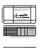
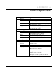
Super Remote Meter Interface (RMI) Board
Isolated Digital Outputs
Number: 4
Features: Programmable, source-driven (active high with
common ground) and short circuit-protected.
Range:
24 VDC, 20 mA per output (jumper setting
:
24 V INT)
100 mA per output with external power supply
(jumper setting
:
24 V EXT)
Update time: 1.0 ms if delay time = 0
100.0 ms if delay time ≠ 0
Relay Outputs
Number: 3
Features: Three relays, programmable, timer function.
Relay 1 has a normally-open contact.
Relays 2 and 3 have 1 normally-open and 1
normally-closed contact.
Rating: 2 A, 24VDC or 250VA, 120VAC
Update time: 1.0 ms if delay time = 0
100.0 ms if delay time ≠ 0
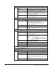
Isolated Analog Outputs
Number: 3
Features: Short circuit-protected, programmable,
software-calibrated.
Range: Output 1: 0 to 10 VDC
Output 2: –0 to +10VDC
Output 3: 0 to 10 VDC (jumper setting
:
V OUT)
0 to 20 mA (jumper setting
:
C OUT)
Load: 10 VDC outputs: RL ≥ 10 kΩ
20 mA output: RL ≤ 500Ω
Crossover frequency: 1 kHz
Carrier frequency: 20 kHz
Resolution: 10 bits
Connection Port to the Regulator Board
34-pin flat cable connector
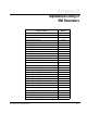
Power Consumption of the RMI Board
24 V supply current: Max. 320 mA with unloaded digital outputs
Additional load: Max. 20mA load current per digital output (4 total)
External 24 V supply: For 20 mA < load current < 100 mA, an external 24
V power supply must be connected to terminals 46
(+) and 51 (–) and the 24V jumper must be set to
24 V EXT.
15 V Not used.