
User guide


4-14
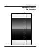
Super Remote Meter Interface (RMI) Board
The RMI board's digital and relay outputs can be individually programmed for on-delay
or off-delay. After the regulator signals an output to turn on or off, the RMI board will
wait for the programmed time delay before the output is turned on or off.
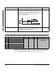
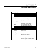
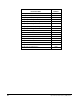
20 = Speed Reference The output is turned on when the absolute value of the
selected speed reference is greater than or equal to Low
Speed Detection (r.056). The output is turned off when
the absolute value of the selected speed reference is less
than the value in r.056 minus the Speed Detection
Hysteresis Band (r.053).
Figure 4.10 – Speed Reference
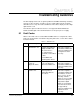
21 = TB Start & Stop The output is turned on when the terminal block Start and
Stop inputs are both closed. The output is turned off
when either of these inputs is open.
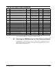
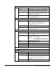
r.040 to r.046 Digital Output Relay Timers
Par. Parameter Name Type Default Step Range
r.040 Digital Output 1 Delay Time Tunable 0 sec 0.1 –999.9 to 999.9 sec
+ on-delay values
– off-delay values
r.041 Digital Output 2 Delay Time
r.042 Digital Output 3 Delay Time
r.043 Digital Output 4 Delay Time
r.044 Relay Output 1 Delay Time
r.045 Relay Output 2 Delay Time
r.046 Relay Output 3 Delay Time
Table 4.5 – Digital Outputs and Relay Outputs Configuration Selections (Continued)
Selection Description Update Time