
User guide

4-10
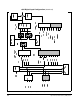
Super Remote Meter Interface (RMI) Board
r.030 Digital Input Configuration
(Continued)
8 Presets
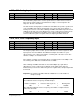
If r.030 = 8, one of Preset Speeds P.031 to P.038 is selected by DIGIN 2 to DIGIN 4.
See table 4.4.
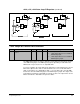
The RMI board's digital and relay outputs are turned on or off as a function of 20
possible comparisons. The values in r.031 through r.037 select the comparison to use
for a particular output.
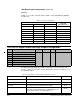
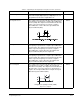
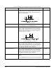
Table 4.4 – Preset Speed Digital Inputs
Digital Inputs (Terminals)
Selected
Speed ReferenceDIGIN 4 (44) DIGIN 3 (43) DIGIN 2 (42)
OFF OFF OFF P.031
OFF OFF ON P.032
OFF ON OFF P.033
OFF ON ON P.034
ON OFF OFF P.035
ON OFF ON P.036
ON ON OFF P.037
ON ON ON P.038
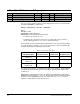
r.031 to r.037 Digital Output and Relay Outputs Configuration
Par. Parameter Name Type Default Step Range
r.031 Digital Output 1 Configuration Config. 0 1 0 to 21 (Table 4.5)
r.032 Digital Output 2 Configuration
r.033 Digital Output 3 Configuration
r.034 Digital Output 4 Configuration
r.035 Relay Output 1 (NO) Configuration
r.036 Relay Output 2 (NO/NC) Configuration
r.037 Relay Output 3 (NO/NC) Configuration
Table 4.5 – Digital Outputs and Relay Outputs Configuration Selections
Selection Description Update Time
0 = Not Used The output is always off.
N/A
1 = Running The output is turned on when the drive is in run.
20 ms
2 = Fault The output is turned on when there is a fault.
20 ms
3 = Aux Input 1 The output is turned on or off (time delayed) as a function
of the Aux 1 input (digital input 4). If digital input 4 is not
programmed as Aux 1, the output will be off.
100 ms