
User guide

4-4
Super Remote Meter Interface (RMI) Board
The outer loop PI regulator output is used to adjust the trim reference. The input to the
PI regulator (ERROR) is computed as:
ERROR = REFERENCE + OFFSET – FEEDBACK
Where:
OFFSET = r.020
FEEDBACK = RMI Analog Input
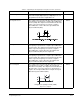
REFERENCE is PI regulator mode-dependent:
•
For Mode 1, the reference is zero.
•
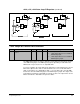
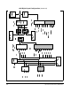
For Mode 2, the selected speed reference is used, but the reference into the
speed summing junction is set to zero as shown in figure 4.2.
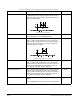
The PI regulator mode is determined by the Trim Reference Source parameter (P.014)
as shown in table 4.2. If P.014 is set to a value other than 8 or 9, the PI regulator will
remain inactive. Figure 4.2 illustrates these modes.
The outer loop PI regulator is evaluated every 20ms in the regulator. The PI regulator
is enabled only when the drive is in run. If the drive is jogged, the PI regulator will
remain reset.
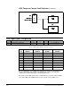
Digital input 4 on the RMI board can be programmed as PI-Enable by setting r.030
(Digital Input Configuration) to 1, 3, 5, or 7. The PI regulator is then enabled only when
the drive is in run and digital input 4 is on. If r.030 is not set to 1, 3, 5, or 7, the PI
regulator is enabled whenever the drive is in run
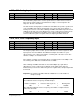
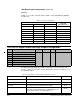
r.020, r.021, r.022 Outer Loop PI Regulator
Par. Parameter Name Type Default Step Range
r.020 PI Regulator Offset Tunable 0 1 –4095 to +4095
r.021 PI Regulator Proportional Gain Tunable 5.00 0.01 0.10 to 50.00
r.022 PI Regulator Integral Gain Tun able 0.05 0.01 0.00 to 10.00
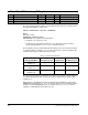
Table 4.2 – Regulator Operating Modes
PI Regulator Mode
PI Regulator
Reference Used
PI Regulator
Offset Used Feedback Used
Mode 1
(P.014 = 8)
Zero r.020 RMI Analog Input
Mode 2
(P.014 = 9)
Selected by P.000 r.020 RMI Analog Input
Inactive
(P.014 8 or 9)
Not Used Not Used Not Used