
User guide


Installation
3-41
3.9 Wiring to the RMI Board Terminal Strip
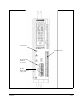
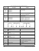
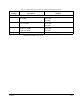
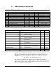
Refer to figure 3.21 for the signal and control I/O terminal connections on the RMI
board. Table 3.9 describes terminal strip connections and related parameters. Refer to
the drive hardware instruction manual for wiring guidelines.
!
ATTENTION:
The user is responsible for conforming with all applicable
local, national, and international codes. Failure to observe this precaution
could result in damage to, or destruction of, the equipment.
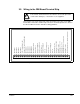
Figure 3.21 – Terminal Connections on the RMI Board
41 42 43 44 45 46 47 48 49 50 51 52 53 54 55 56 57 58 59 60 61 62 63 64 65 66 67 68 69
Digital Input 1
Digital Input 2
Digital Input 3
Digital Input 4
+24 V (for digital inputs only)
External +24 V Input for Digital Outputs
Digital Output 1
Digital Output 2
Digital Output 3
Digital Output 4
Digital Output Common
Relay 1 Common
Relay 1 Normally Open
Relay 2 Normally Closed
Relay 2 Common
Relay 2 Normally Open
Not Used
Relay 3 Normally Closed
Relay 3 Common
Relay 3 Normally Open
Not Used
Analog Input: 0 to 10 V
Analog Input: 0 (4) to 20 mA
Analog I/O Common
Analog Output 1: 0 to 10 V
Analog Output 2: +/-10 V
Analog Output 3: 0 to 10 V/0 to 20 mA
Analog I/O Common
Frequency Input (Ground = Analog I/O Common)