
User guide

3-32
Super Remote Meter Interface (RMI) Board
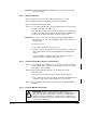
Step 1. Shut Down the Drive
Step 1.1 Disconnect, lock out, and tag all incoming power to the drive.
Step 1.2 Wait five minutes for the DC bus capacitors to discharge.
Important: Read and understand the warning labels on the inside of the drive before
proceeding.
Step 2. Verify That the DC Bus Capacitors are Discharged
Step 2.1 Open the drive’s outer cabinet door.
Step 2.2 Lower the plastic terminal strip shield at the top of the drive.
Step 2.3 Use a voltmeter to verify that there is no voltage at the drive’s AC input
power terminals, R, S, and T.
Step 2.4 Replace the plastic terminal strip shield.
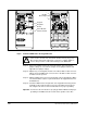
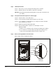
Step 2.5 Ensure that the DC bus capacitors are discharged. To check
DC bus potential:
a. Stand on a non-conductive surface and wear insulated gloves. (600 V)
b. Use a voltmeter to check the DC bus potential at the Voltmeter Test
Points on the Power Module Interface board. See figure 3.16.
Step 3. Remove the Keypad Bracket from the Drive
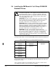
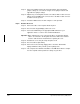
Refer to figure 3.16 for component locations.
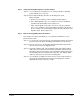
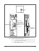
Figure 3.16 – RMI Board Location in 200 to 400HP @ 460VAC Drives
RE SET
PRO GRAM
REVERSE
FOR WAR D
AUTO
JOG
REMOTE
RUNNING
Password
TOR QUE
Hz
RPM
Kw
AMP S
VOLT S
STO P
START
ENTER
GND
GND
DC–
DC+
DC–
DC+
WT1 WT2
V
RL1
W
WT3
RST
SL2 T
Wiring Tray
DANG ER
U
POWER CONNECTIONS
FULL SHIELD TABS IN AND ROTATE SHIELD OUT
CONNECT USING 360MCM TWO HOLE TERMINAL LUGS
TORQUE TO 325IN-LB
RMI Board
Regulator
Board
Keypad
Power Module
Interface Board
Side View
(Enlarged)
Front View