
User guide

Installation
3-15
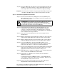
Step 5.6 Reinstall the cover. Align all cover screws into the heat sink before
tightening any of them.
To maintain the integrity of NEMA 4X/12 drives, sequentially tighten the
cover screws to ensure even compression of the gaskets. Do not exceed
2.2 Nm (20 in-lb) of torque on these screws.
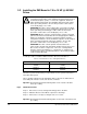
Step 5.7 Remove the lockout and tag. Apply power to the drive. SELF will be
displayed while the drive performs power-up diagnostics.
This completes the hardware installation of the RMI board. Refer to chapter 4 for the
required software parameter settings for your drive.
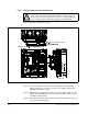
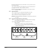
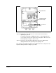
Figure 3.6 – 1 to 20HP @ 230 V GV3000/SE Drive
Keypad Bracket
Regulator Board
Ter minal Str ip
Power Terminal
Strip