
User guide


3-6
Super Remote Meter Interface (RMI) Board
Step 4. Install the RMI Board in the Keypad Bracket
Refer to figure 3.2 for component locations.
Step 4.1 Remove the RMI board from its anti-static wrapper and verify that the
jumper settings are correct. Refer to figure 2.1 for jumper locations and
appendix A for jumper settings.
Step 4.2 Align the key on the Regulator board’s 34-conductor ribbon cable connector
with the slot in the RMI board’s connector. Press the ribbon cable connector
in until it locks into position.
Step 4.3 Route the 26-conductor ribbon cable for the Current Feedback board out of
the side of the keypad bracket.
Step 4.4 Align the RMI board on the four mounting tabs on the keypad bracket. Make
sure that the ribbon cable is not pinched between the keypad bracket and
the RMI board.
!
ATTENTION:The RMI board contains components that are
static-sensitive. An anti-static wrist band should be worn by any person
who touches the board’s components, connectors, or wiring. Failure to
observe this precaution could result in damage to the RMI board.
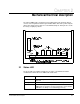
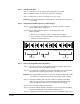
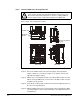
Figure 3.2 – RMI Board Location in 1 to 5HP @ 460VAC Drives
Side View
Front View
Top View
Regulator
Board
20
16
REVERSE
AUTO
REMOTE
RUNNING
FOR WARD
RPM
Password
TORQUE
Kw
Hz
JOGAMPS
VOLTS
PROG RAMPROG RAM
AUTO
Reverse
JOG
RUN
ENTER
START
RESET
STOP
Forward
RMI Board
Current Feedback
Board
RMI Board