
User guide

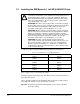

2-2
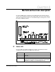
Super Remote Meter Interface (RMI) Board
2.2 Terminal Strip Signals
The following signals are available at the terminal strip. Refer to figure 3.21 for
terminal identification.
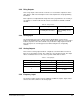
2.2.1 Digital Inputs
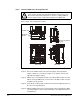
Four 24 volt DC digital inputs provide additional speed reference options. The inputs
are active high. A 24 VDC supply is provided by the RMI board for use with the digital
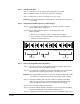
inputs. The supply is short circuit- and overvoltage-protected. See figure 2.2.
Important:
This supply should not be used as an external supply for anything other
than the four digital inputs.
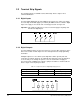
2.2.2 Digital Outputs
Four 24 volt digital outputs are turned on and off as a result of data comparisons in the
drive. Refer to table 3.9 and chapter 4 for the related parameters and programming
information.
All digital outputs are source-driven (active high with common ground) and short
circuit-protected. Each output has an adjustable time delay that can be programmed
as an on-delay or an off-delay. An option to select an external 24 volt supply for
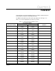
increased current capability at the outputs is jumper-selectable as shown in table 2.1.
Refer to figure 2.1 for the jumper location.
Figure 2.2 – Digital Input Circuit
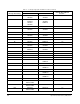
Table 2.1 – Jumper Selections for Digital Output Supply Source
Jumper Selection 24VDC Supply Source Output Result
24 V INT Internal 20mA per output
24 V EXT External 100mA per output
Figure 2.3 – Digital Output Circuit