Super Remote Meter Interface (RMI) Board For Use With GV3000/SE and VTAC 7 Drives M/N 2SI3000 M/N 2SI3000E Instruction Manual D2-3341-2
The information in this manual is subject to change without notice. Throughout this manual, the following notes are used to alert you to safety considerations: ! ATTENTION: Identifies information about practices or circumstances that can lead to personal injury or death, property damage, or economic loss. Important: Identifies information that is critical for successful application and understanding of the product.
CONTENTS Contents Chapter 1 Introduction 1.1 Where to Find Additional Information .............................................................. 1-1 1.2 Getting Assistance from Reliance Electric....................................................... 1-2 Chapter 2 Mechanical/Electrical Description 2.1 Status LED ...................................................................................................... 2-1 2.2 Terminal Strip Signals ............................................................
II Super Remote Meter Interface (RMI) Board
List of Figures Figure 2.1 – RMI Board ............................................................................................ 2-1 Figure 2.2 – Digital Input Circuit ............................................................................... 2-2 Figure 2.3 – Digital Output Circuit............................................................................. 2-2 Figure 3.1 – DC Bus Voltage Terminals (1 to 5HP @ 460VAC) .............................. 3-5 Figure 3.
IV Super Remote Meter Interface (RMI) Board
List of Tables Table 2.1 – Jumper Selections for Digital Output Supply Source............................. 2-2 Table 2.2 – Relay Contacts ...................................................................................... 2-3 Table 2.3 – Analog Outputs ...................................................................................... 2-3 Table 3.1 – Locating the Appropriate Installation Procedure ................................... 3-1 Table 3.2 – Model Numbers for 1 to 5HP@460VAC Drives.............
VI Super Remote Meter Interface (RMI) Board
CHAPTER 1 Introduction The optional Remote Meter Interface (RMI) board provides an extended set of terminal strip inputs and outputs for the GV3000/SE™ drive and the VTAC 7™ HVAC drive. When the drive control source is the terminal strip (P.000 = rE), the RMI board can be used to provide additional speed reference selections. The RMI board also provides an outer PI regulator that is used to adjust trim.
• GV3000/SE 230 VAC 30-100 HP General Purpose (Volts/Hertz) and Vector Duty Drive Software Start-Up and Reference Manual (D2-3416) • GV3000/SE AC Drive Hardware Reference, Installation, and Troubleshooting 30-100 HP @ 230 VAC (D2-3417) • GV3000/SE AC General Purpose (Volts/Hertz) and Vector Duty Bookshelf Drive Software Start-Up and Reference Manual (D2-3426) • GV3000/SE AC Bookshelf Power Modules Hardware Reference, Installation, and Troubleshooting (D2-3427) 1.
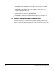
CHAPTER 2 Mechanical/Electrical Description The optional RMI board is a printed circuit assembly that mounts inside the drive. It connects to the Regulator board through a flexible ribbon cable and is powered by the drive power supply. Refer to figure 2.1 for the RMI board layout. This figure also shows the factory-set jumper positions.
2.2 Terminal Strip Signals The following signals are available at the terminal strip. Refer to figure 3.21 for terminal identification. 2.2.1 Digital Inputs Four 24 volt DC digital inputs provide additional speed reference options. The inputs are active high. A 24 VDC supply is provided by the RMI board for use with the digital inputs. The supply is short circuit- and overvoltage-protected. See figure 2.2.
2.2.3 Relay Outputs Three relay outputs can be turned on and off as a result of data comparisons in the drive. Refer to table 3.9 and chapter 4 for the related parameters and programming information. Each output has an adjustable time delay that can be programmed as an on-delay or an off-delay as shown in table 2.2. All contacts are rated at 2A, 24VDC or 250VA, 120VAC. Table 2.
2-4 Super Remote Meter Interface (RMI) Board
CHAPTER 3 Installation Contact Reliance if the drive installation must be in compliance with the European Community Electromagnetic Compatibility Standards. The RMI board installation procedure differs depending on the drive type. Use table 3.1 to locate the appropriate procedure for your drive. Table 3.1 – Locating the Appropriate Installation Procedure Drive Model Number Use the Procedure in Section … Horsepower Rating GV3000/SE VTAC 7 1 1V21xx 1V24xx 1H21xx 1H22xx 3.
Table 3.1 – Locating the Appropriate Installation Procedure (Continued) Drive Model Number Use the Procedure in Section … Horsepower Rating GV3000/SE VTAC 7 20 20V41xx 20V42xx 20H41xx 20H42xx 3.5 25 25G41xx 25G42xx 25V41xx 25V42xx 25H41xx 25H42xx 25W21xx 3.5 30 30V20xx 30W21xx 3.4 30 30V41xx 30V42xx 30H41xx 30H42xx 3.5 40 40V20xx 40W21xx 3.4 40 40V41xx 40V42xx 40H41xx 40H42xx 3.5 50 50R41xx — 3.6 50 50T41xx — 3.6 50 50V20xx 50W21xx 3.
Table 3.1 – Locating the Appropriate Installation Procedure (Continued) Drive Model Number Horsepower Rating GV3000/SE VTAC 7 Use the Procedure in Section … 350 350V41xx 350V41xxDS 350H41xx 3.7 400 400V41xx 400V41xxDS 400H41xx 3.7 2 to 15 Amp 31ER40xx 31ET40xx 38ER40xx 38ET40xx 55ER40xx 55ET40xx 85ER40xx 85ET40xx 126ER40xx 126ET40xx 150ER40xx 150ET40xx — 3.8 24 to 30 Amp 240ER40xx 240ET40xx 300ER40xx 300ET40xx — 3.8 43 Amp 430ER40xx 430ET40xx — 3.
3.1 Installing the RMI Board in 1 to 5HP@460VAC Drives ! ATTENTION: Only qualified electrical personnel familiar with the construction and operation of this equipment and the hazards involved should install, adjust, operate, or service this equipment. Read and understand this manual and other applicable manuals in their entirety before proceeding. Failure to observe this precaution could result in severe bodily injury or loss of life.
Step 1. Shut Down the Drive Step 1.1 Disconnect, lock out, and tag all incoming power to the drive. Step 1.2 Wait five minutes for the DC bus capacitors to discharge. Step 1.3 Remove the cover by loosening the four cover screws. Important: Read and understand the warning labels on the inside of the drive before proceeding. Step 2. Verify That the DC Bus Capacitors are Discharged Step 2.1 Use a voltmeter to verify that there is no voltage at the drive’s AC input power terminals (R/L1, S/L2, T/L3). Step 2.
Step 4. Install the RMI Board in the Keypad Bracket ! ATTENTION: The RMI board contains components that are static-sensitive. An anti-static wrist band should be worn by any person who touches the board’s components, connectors, or wiring. Failure to observe this precaution could result in damage to the RMI board. Refer to figure 3.2 for component locations.
Step 4.5 Fasten the RMI board to the right side of the keypad bracket using the two metal M3 screws and lock washers for proper grounding. Fasten the left side using the two 6-32 screws and lock washers for proper grounding. Important: You must use the lock washers to properly ground the RMI board. Improper grounding of the RMI board can result in erratic operation of the drive. Step 5. Reinstall the Keypad Bracket in the Drive Step 5.
3.2 Installing the RMI Board in 7.5 to 10 HP @ 460VAC Drives ! ATTENTION: Only qualified electrical personnel familiar with the construction and operation of this equipment and the hazards involved should install, adjust, operate, or service this equipment. Read and understand this manual and other applicable manuals in their entirety before proceeding. Failure to observe this precaution could result in severe bodily injury or loss of life.
Step 2. Verify That the DC Bus Capacitors are Discharged Step 2.1 Use a voltmeter to verify that there is no voltage at the drive’s AC input power terminals (R/L1, S/L2, T/L3). Step 2.2 Ensure that the DC bus capacitors are discharged. To check DC bus potential: a. Stand on a non-conductive surface and wear insulated gloves. b. Use a voltmeter to measure the DC bus potential at the DC bus power terminals shown in figure 3.3.
Step 4. Install the RMI Board in the Keypad Bracket ! ATTENTION: The RMI board contains components that are static-sensitive. An anti-static wrist band should be worn by any person who touches the board’s components, connectors, or wiring. Failure to observe this precaution could result in damage to the RMI board. Refer to figure 3.4 for component locations. Current Feedback Board RMI Board Regulator Board Top View Side View Front View Figure 3.4 – RMI Board Location in 7.5 to 10HP Drives Step 4.
Step 4.4 Align the RMI board on the four mounting tabs on the keypad bracket. Make sure that the ribbon cable is not pinched between the keypad bracket and the RMI board. Step 4.5 Fasten the RMI board to the right side of the keypad bracket using the two metal M3 screws and lock washers for proper grounding. Fasten the left side using the two 6-32 screws and lock washers for proper grounding. Important: You must use the lock washers to properly ground the RMI board.
3.3 Installing the RMI Board in 1 to 20HP@230VAC Drives ! ATTENTION: Only qualified electrical personnel familiar with the construction and operation of this equipment and the hazards involved should install, adjust, operate, or service this equipment. Read and understand this manual and other applicable manuals in their entirety before proceeding. Failure to observe this precaution could result in severe bodily injury or loss of life.
If the drive is panel-mounted, this procedure will be easier to perform if the drive is removed from the panel. Unless otherwise indicated, keep all hardware that is removed. You will need it for reassembly. This includes screws, lock washers, and rivets. Important: Read and understand the warning labels on the outside of the drive before proceeding. Step 1. Shut Down the Drive Step 1.1 Disconnect, lock out, and tag all incoming power to the drive. Step 1.
Step 3. Remove the Keypad Bracket from the Drive Step 3.1 Record connections to the Regulator board terminal strip if they must be disconnected to remove the keypad bracket. Step 3.2 Use a magnetic screwdriver to remove the M4 x 10 screws that fasten the bottom of the keypad support bracket to the drive. Step 3.3 Spread the retaining clips on the Regulator board ribbon cable (on the right side) to disconnect it from the Base Board. Step 3.4 Remove the keypad bracket.
Keypad Bracket Regulator Board Terminal Strip Power Terminal Strip Figure 3.6 – 1 to 20HP @ 230 V GV3000/SE Drive Step 5.6 Reinstall the cover. Align all cover screws into the heat sink before tightening any of them. To maintain the integrity of NEMA 4X/12 drives, sequentially tighten the cover screws to ensure even compression of the gaskets. Do not exceed 2.2 Nm (20 in-lb) of torque on these screws. Step 5.7 Remove the lockout and tag. Apply power to the drive.
3.4 Installing the RMI Board in 30 to 100HP@230VAC and 75 to 200 @ 460VAC Drives ! ATTENTION: Only qualified electrical personnel familiar with the construction and operation of this equipment and the hazards involved should install, adjust, operate, or service this equipment. Read and understand this manual and other applicable manuals in their entirety before proceeding. Failure to observe this precaution could result in severe bodily injury or loss of life.
Step 1. Shut Down the Drive Step 1.1 Disconnect, lock out, and tag all incoming power to the drive. Step 1.2 Wait five minutes for the DC bus capacitors to discharge. Step 1.3 VTAC 7 drives: Open the drive’s outer cabinet door. Important: Read and understand the warning labels on the inside of the drive before proceeding. Step 2. Verify That the DC Bus Capacitors are Discharged Step 2.
Step 3. Remove the Keypad Bracket from the Drive Step 3.1 VTAC 7 drives: Remove the Power Module from the drive cabinet. Step 3.2 If the drive has: • A Regulator board and terminal cover: Remove the three M4 screws from the cover plate over the Regulator board. Remove the cover. See figure 3.8. • A terminal cover only: If you have this type of drive, this procedure is easier to perform if you lay the drive on its side. Remove the side cover from the drive.
Step 4. Install the RMI Board in the Keypad Bracket ! ATTENTION: The RMI board contains components that are static-sensitive. An anti-static wrist band should be worn by any person who touches the board’s components, connectors, or wiring. Failure to observe this precaution could result in damage to the RMI board. Refer to figures 3.8 and 3.9 for component locations. Step 4.1 Remove the RMI board from its anti-static wrapper and verify that the jumper settings are correct. Refer to figure 2.
Regulator Board Front Ribbon Cable Connecting Regulator Board and Base Board Metal Screw Ribbon Cable Connecting Regulator Board and RMI Board Top View RMI Board Back Side of Regulator Board To Base Board Insulator Ribbon Cable Connector to Connect Base Board Ribbon Cable Connector to Connect RMI Board Ribbon Cable Connector to Connect Keypad Plastic Rivet Rear View of Regulator Board Terminal Strip Figure 3.9 – Regulator Board’s Connection to RMI Board, Keypad, and Base Board Step 5.
3.5 Installing the RMI Board in 15 to 25HP and 25 to 60HP @ 460VAC Drives ! ATTENTION: Only qualified electrical personnel familiar with the construction and operation of this equipment and the hazards involved should install, adjust, operate, or service this equipment. Read and understand this manual and other applicable manuals in their entirety before proceeding. Failure to observe this precaution could result in severe bodily injury or loss of life.
Step 1. Shut Down the Drive Step 1.1 Disconnect, lock out, and tag all incoming power to the drive. Step 1.2 Wait five minutes for the DC bus capacitors to discharge. Step 1.3 Remove the cover by loosening the four cover screws. Important: Read and understand the warning labels on the inside of the drive before proceeding. Step 2. Verify That the DC Bus Capacitors are Discharged Step 2.1 Use a voltmeter to verify that there is no voltage at the drive’s AC input power terminals (R/L1, S/L2, T/L3). Step 2.
Step 3. Remove the Keypad Bracket from the Drive See figure 3.12 (15 to 25HP @ 460VAC) or 3.13 (25 to 60HP @ 460VAC) for part locations. Step 3.1 Record connections to the Regulator board terminal strip if they must be disconnected to remove the keypad bracket. Step 3.2 Loosen the thumb screw on the left side of the keypad bracket. Hold the bracket on the left and lift the bracket up and to the left to separate it from the keypad support bracket.
Regulator Board Front View RMI Board Top View Figure 3.13 – RMI Board Location in 25 to 60 HP @ 460VAC Drives Step 4.5 Align the key on the Regulator board’s 34-conductor ribbon cable connector with the slot in the RMI board’s connector. Press the ribbon cable connector in until it locks into position. Step 4.6 Align the RMI board on the four mounting tabs on the keypad bracket. Make sure that the ribbon cable is not pinched between the keypad bracket and the RMI board. Step 4.
Step 5.4 NEMA 4X/12 drives only: Before installing the cover, check that the gaskets on the cover are flat and within the gasket channels. Step 5.5 Reinstall the cover. Align all cover screws into the heat sink before tightening any of them. To maintain the integrity of NEMA 4X/12 drives, sequentially tighten the cover screws to ensure even compression of the gaskets. Do not exceed 2.2 Nm (20 in-lb) of torque on these screws. Step 5.6 Remove the lockout and tag. Apply power to the drive.
3.6 Installing the RMI Board in 50 to 100HP and 100 to 150HP @ 460VAC Drives (GV3000/SE Drives Only) ! ATTENTION: Only qualified electrical personnel familiar with the construction and operation of this equipment and the hazards involved should install, adjust, operate, or service this equipment. Read and understand this manual and other applicable manuals in their entirety before proceeding. Failure to observe this precaution could result in severe bodily injury or loss of life.
Step 2. Verify That the DC Bus Capacitors are Discharged Step 2.1 Use a voltmeter to verify that there is no voltage at the drive’s AC input power terminals (1L1, 1L2, 1L3). Step 2.2 Ensure that the DC bus capacitors are discharged. To check DC bus potential: a. Stand on a non-conductive surface and wear insulated gloves. b. 50 to 100 HP @ 460 V only: Use a voltmeter to measure the DC bus potential at the diode bridge. Refer to figure 3.14. c.
– DC Bus Measuring Points + 45 47 45 47 Keypad Regulator Board Power Module Interface Board Figure 3.14 – Drive Components and Locations (50 to 100HP @ 460VAC) Step 4. Install the RMI Board in the Keypad Bracket ! ATTENTION: The RMI board contains components that are static-sensitive. An anti-static wrist band should be worn by any person who touches the board’s components, connectors, or wiring. Failure to observe this precaution could result in damage to the RMI board. Step 4.
Power Module Interface Board Fuses DC Bus Measuring Points Regulator Panel DC bus measuring points are behind the Regulator Panel on the Power Module Interface board. Power Module Interface Board Keypad Regulator Board Power Module Interface Board Figure 3.15 – Drive Components and Locations in 100 to 150HP @ 460VAC Drives Step 5. Reinstall the Keypad Bracket in the Drive Step 5.1 Reconnect the keypad bracket to the hinged mounting panel using the four screws and lock washers removed earlier.
Step 5.3 100 to 150 HP drives only: Align the Power Module Interface board on the eight plastic standoffs on the back of the mounting panel. Carefully press it into place. Make sure that good contact has been made with the two grounding standoffs. Step 5.4 Route the Regulator board’s 60-conductor ribbon cable through the slot in the hinged mounting panel to the connector on the Power Module Interface board. Align the two connectors.
3.7 Installing the RMI Board in 200 to 400 HP @ 460VAC Drives ! ATTENTION: Only qualified electrical personnel familiar with the construction and operation of this equipment and the hazards involved should install, adjust, operate, or service this equipment. Read and understand this manual and other applicable manuals in their entirety before proceeding. Failure to observe this precaution could result in severe bodily injury or loss of life.
Step 1. Shut Down the Drive Step 1.1 Disconnect, lock out, and tag all incoming power to the drive. Step 1.2 Wait five minutes for the DC bus capacitors to discharge. Important: Read and understand the warning labels on the inside of the drive before proceeding. Step 2. Verify That the DC Bus Capacitors are Discharged Step 2.1 Open the drive’s outer cabinet door. Step 2.2 Lower the plastic terminal strip shield at the top of the drive. Step 2.
Step 3.1 Record connections to the Regulator board terminal strip if they must be disconnected to remove the keypad bracket. Step 3.2 Use a magnetic screwdriver to remove the four screws and lock washers that fasten the keypad bracket to the hinged mounting panel. Hold the keypad bracket as you remove the screws. Step 3.3 Disconnect the Regulator board ribbon cable from the Power Module Interface board. Step 4.
3.8 Installing the RMI Board in 2 to 43 Amp GV3000/SE Bookshelf Drives ! ATTENTION: Only qualified electrical personnel familiar with the construction and operation of this equipment and the hazards involved should install, adjust, operate, or service this equipment. Read and understand this manual and other applicable manuals in their entirety before proceeding. Failure to observe this precaution could result in severe bodily injury or loss of life.
Important: Read and understand the warning labels on the outside of the drive before proceeding. Step 1. Shut Down the Drive Step 1.1 Disconnect, lock out, and tag all incoming power to the drive. Step 1.2 Wait five minutes for the DC bus capacitors to discharge. Step 1.3 Disconnect all faceplate wiring. Step 1.4 2 to 15 A drives: Remove the cover by removing the cover screw on the faceplate of the drive. See figure 3.17.
Step 3.1 Remove the RMI board from its anti-static wrapper and verify that the jumper settings are correct. Refer to figure 2.1 for jumper locations and appendix A for jumper settings. Step 3.2 Align the key on the Regulator board’s 34-conductor ribbon cable connector with the slot in the RMI board’s connector. Press the ribbon cable connector in until it locks into position. Step 3.3 Fasten the RMI board to the drive using the screws provided. Step 4. Reattach the Cover Step 4.
Cover Screw Breakout Panel AC Input Power Terminals (L1, L2, L3) DC Bus Measuring Point (–)45, (+)47 Figure 3.
Front Panel Screw Cover Screw Breakout Panel / / / 8 9 : AC Input Power Terminals (L1, L2, L3) DC Bus Measuring Point (-)45, (+)47 Front Panel Screw Figure 3.
Front Panel Screw Cover Screw AC Input Power Terminals (L1, L2, L3) Breakout 3( / / / 8 9 : Panel DC Bus Measuring Point (-)45, (+)47 Front Panel Screw Figure 3.
Keypad/Display Cable Connector Regulator Board Regulator Board Ribbon Cable RMI Board Drive shown with cover and front panel removed. Figure 3.
3.9 Wiring to the RMI Board Terminal Strip ATTENTION: The user is responsible for conforming with all applicable local, national, and international codes. Failure to observe this precaution could result in damage to, or destruction of, the equipment.
Table 3.9 – Wiring Signal and Control I/O to the RMI Board Terminal Strip Terminal Number Related Parameters, Specifications, and Jumpers Description Digital Inputs, Control Voltage Output 41 42 43 44 Digital Input 1 Digital Input 2 Digital Input 3 Digital Input 4 The four digital inputs are configured using parameter r.030. 45 +24 VDC Supply, Control Voltage Output Current-limited and isolated. This supply should not be used as an external supply for anything other than the four digital inputs.
Table 3.9 – Wiring Signal and Control I/O to the RMI Board Terminal Strip (Continued) Terminal Number Related Parameters, Specifications, and Jumpers Description Analog Outputs 65 Analog Output No. 1 0 to 10 VDC Configuration: r.001 Offset: r.002 Gain: r.003 66 Analog Output No. 2 –10 to +10 VDC Configuration: r.004 Offset: r.005 Gain: r.006 67 Analog Output No. 3 V OUT: 0 to 10 VDC C OUT: 0 to 20 mA Configuration: r.007 Offset: r.008 Gain: r.
3-44 Super Remote Meter Interface (RMI) Board
CHAPTER 4 Programming Reference A set of parameters used specifically with the RMI board is accessible when the RMI board is connected to the drive. The parameters are in the Second Menu, as shown in figure 4.1. RMI parameters have a lower case r as the first character. If the RMI board is not properly connected, the r parameters will not be displayed. This chapter describes the r parameters. All other drive parameters are described in the drive software instruction manual.
4.1 RMI Parameter Descriptions r.001 to r.099 Analog Outputs Par. Parameter Name Type Default Step Range r.001 Analog Output 1 Source Config. 1 1 0 to 8 (Table 4.1) r.002 Analog Output 1 Offset Tunable 0 1 –4095 to +4095 r.003 Analog Output 1 Gain Tunable 1.000 0.001 0.100 to 5.000 r.004 Analog Output 2 Source Config. 2 1 0 to 8 (Table 4.1) r.005 Analog Output 2 Offset Tunable 0 1 –4095 to +4095 r.006 Analog Output 2 Gain Tunable 1.000 0.001 0.100 to 5.000 r.
r.010, r.011 Analog Input Par. Parameter Name Type Default Step Range r.010 Analog Input Offset Tunable 0 1 – 3700 to +3700 r.011 Analog Input Gain Tunable 1.000 0.001 – 5.000 to +5.000 The 10-bit analog input can be used for speed reference or trim reference. Refer to figure 4.4. The input is jumper-selected between voltage or current signals in the range 0 to 10 volts or 0 to 20 mA. The data from the analog input is normalized so that 4095 corresponds to positive full scale.
r.020, r.021, r.022 Outer Loop PI Regulator Par. Parameter Name Type Default Step Range r.020 PI Regulator Offset Tunable 0 1 –4095 to +4095 r.021 PI Regulator Proportional Gain Tunable 5.00 0.01 0.10 to 50.00 r.022 PI Regulator Integral Gain Tunable 0.05 0.01 0.00 to 10.00 The outer loop PI regulator output is used to adjust the trim reference. The input to the PI regulator (ERROR) is computed as: ERROR = REFERENCE + OFFSET – FEEDBACK Where: OFFSET = r.
r.020, r.021, r.022 Outer Loop PI Regulator (continued) 6SHHG 3 'UDZ 'UDZ 'UDZ 6SHHG 3 5HIHUHQFH 6SHHG 3 5HIHUHQFH 5HIHUHQFH RMI 3 3, 7ULP P.015 Offset Offset 50,B$,1 RMI 3 3 3, 7ULP 7ULP P.015 P.015 50,B$,1 U U 0RGH 3, 5HJXODWRU 1RW 8VHG 0RGH Figure 4.2 – PI Regulator Operating Modes r.025 Torque or Current Limit Selection Par. r.
r.025 Torque or Current Limit Selection (Continued) U $QDORJ ,QSXW )UHTXHQF\ ,QSXW 9HFWRU 7RUTXH /LPLW 9 +] &XUUHQW /LPLW Figure 4.3 – Torque or Current Limit Selection r.030 Digital Input Configuration Par. r.030 Parameter Name Digital Input Configuration Type Default Step Range Config. 0 1 0 to 8 (Table 4.3) Table 4.3 – Digital Input Configuration Selections for r.030 r.
r.030 Digital Input Configuration (Continued) Figure 4.4 displays the options for selecting the speed reference when the RMI board is used. Note that even with the additional options for controlling the MOP and Preset Speeds, there is still only one MOP and there are still only eight preset speeds for selection. The shaded areas in figure 4.4 show the additional speed reference options when the RMI board is installed in the drive. Note that when P.
4-8 50, ,QSXW 50, ,QSXW 50, ,QSXW 'LJLWDO ,QSXW 'LJLWDO ,QSXW 'LJLWDO ,QSXW U 3 5HVHW 3 DQG U 8VHG IRU ERWK 3 3 WR 3 3UHVHW 6SHHGV 023 3UHVHWV 3UHVHWV 3UHVHWV 3UHVHWV 3UHVHWV 3HVHWV 3UHVHWV 023 ,QSXW )UHTXHQF\ 50, $QDORJ U &RQILJXUDWLRQ 'LJLWDO ,QSXW 023 3UHVHWV $QDORJ ,QSXW 0 50, 3, 5HJXODWRU 50, $QDORJ )UHTXHQF\ ,QSXW 50, )UHTXHQF\ ,QSXW 50, $QDORJ ,QSXW 7RUTXH )HHGED
r.030 Digital Input Configuration (Continued) Aux Input 2 DIGIN 3 can be programmed as an auxiliary input (Aux Input 2) by setting r.030 = 0, 1, 4, or 5. This auxiliary input can be used to turn any digital output or relay output on and off with an on-delay or an off-delay using the corresponding time delay parameter (r.040 through r.046). If r.030 = 0, 1, 4, or 5 and DIGIN 3 is on, the Aux Input 2 function is enabled to control the selected digital output or relay output. If r.
r.030 Digital Input Configuration (Continued) 8 Presets If r.030 = 8, one of Preset Speeds P.031 to P.038 is selected by DIGIN 2 to DIGIN 4. See table 4.4. Table 4.4 – Preset Speed Digital Inputs Digital Inputs (Terminals) DIGIN 4 (44) DIGIN 3 (43) DIGIN 2 (42) Selected Speed Reference OFF OFF OFF P.031 OFF OFF ON P.032 OFF ON OFF P.033 OFF ON ON P.034 ON OFF OFF P.035 ON OFF ON P.036 ON ON OFF P.037 ON ON ON P.038 r.031 to r.
Table 4.5 – Digital Outputs and Relay Outputs Configuration Selections (Continued) Selection Description Update Time 4 = Aux Input 2 The output is turned on or off (time delayed) as a function of the Aux 2 input (digital input 3). If digital input 3 is not programmed as Aux 2, the output will be off. 100 ms 5 = Speed Level 1 The output is turned on when the absolute value of speed or frequency is greater than or equal to Speed Detection Level 1 (r.050).
Table 4.5 – Digital Outputs and Relay Outputs Configuration Selections (Continued) Selection 9 = Speed Reached Description Update Time The output is turned on when the absolute value of commanded speed or frequency minus actual speed or frequency is less than or equal to the Speed Detection Hysteresis Band (r.053). + 100 ms + 5 + +\VWHUHVLV U 5 6SHHG 5HIHUHQFH Figure 4.7 – Speed Reached 10 = Remote The output turns on when any control source other than the local keypad is selected (P.
Table 4.5 – Digital Outputs and Relay Outputs Configuration Selections (Continued) Selection 15 = Reverse Rotation Description For V/Hz regulation, the output is turned on when the drive is commanding reverse rotation. If the drive is stopped, the output is off, regardless of the commanded direction. If running forward, the output remains off until the drive ramps to zero, then changes direction.
Table 4.5 – Digital Outputs and Relay Outputs Configuration Selections (Continued) Selection 20 = Speed Reference Description Update Time The output is turned on when the absolute value of the selected speed reference is greater than or equal to Low Speed Detection (r.056). The output is turned off when the absolute value of the selected speed reference is less than the value in r.056 minus the Speed Detection Hysteresis Band (r.053).
r.050 to r.066 Digital Output Comparison Par. Parameter Name Type Default Step Range r.050 Speed Detection Level 1 Tunable 150 RPM (Vector) 5.0 Hz (V/Hz) 1 RPM 0.1 Hz 0 RPM to P.004 0.5 Hz to P.004 r.051 Speed Detection Level 2 Tunable 150 RPM (Vector) 5.0 Hz (V/Hz) 1 RPM 0.1 Hz 0 RPM to P.004 0.5 Hz to P.004 r.052 Speed Detection Level 3 Tunable 150 RPM (Vector) 5.0 Hz (V/Hz) 1 RPM 0.1 Hz 0 RPM to P.004 0.5 Hz to P.004 r.
4-16 Super Remote Meter Interface (RMI) Board
CHAPTER 5 Troubleshooting Guidelines The drive displays fault codes to signal a problem in the RMI board during self tuning (start up) or drive operation. If a fault occurs, the outputs will be turned off and the drive will coast to a stop. The fault code will flash on the drive's display as a three-digit alpha-numeric code. Note that the option to hold last reference is not supported with the RMI board. Parameter P.062 (Option Port: Communication Loss Response) does not apply. 5.1 Fault Codes Table 5.
5-2 Super Remote Meter Interface (RMI) Board
APPENDIX A Technical Specifications Isolated Digital Inputs Number 4 Features Active high, programmable, overvoltage-protected. Range: 4 mA, 24 VDC Sample time: 1.0ms; the regulator is updated if the input stays in the same state for 3.0 ms. Supply: 24 VDC (short circuit protected) is available from the RMI board. This supply must not be used for powering external circuits. Isolated Analog Input Number: 1 Features: 10-bit resolution, overvoltage-protected, programmable, software-calibrated.
Isolated Digital Outputs Number: 4 Features: Programmable, source-driven (active high with common ground) and short circuit-protected. Range: 24 VDC, 20 mA per output (jumper setting: 24 V INT) 100 mA per output with external power supply (jumper setting: 24 V EXT) Update time: 1.0 ms if delay time = 0 100.0 ms if delay time ≠ 0 Relay Outputs Number: 3 Features: Three relays, programmable, timer function. Relay 1 has a normally-open contact.
APPENDIX B Alphabetical Listing of RMI Parameters Parameter Name Parameter Number Analog Input Gain r.011 Analog Input Offset r.010 Analog Output 1 Gain r.003 Analog Output 1 Offset r.002 Analog Output 1 Source r.001 Analog Output 2 Gain r.006 Analog Output 2 Offset r.005 Analog Output 2 Source r.004 Analog Output 3 Gain r.009 Analog Output 3 Offset r.008 Analog Output 3 Source r.007 Current Detection Hysteresis r.060 Current Detection Level 1 r.057 Current Detection Level 2 r.
Parameter Name B-2 Parameter Number PI Regulator Offset r.020 PI Regulator Proportional Gain r.021 Relay Output 1 (NO) Configuration r.035 Relay Output 1 Delay Time r.044 Relay Output 2 (NC/NO) Configuration r.036 Relay Output 2 Delay Time r.045 Relay Output 3 (NO/NC) Configuration r.037 Relay Output 3 Delay Time r.046 Speed Detection Hysteresis Band r.053 Speed Detection Level 1 r.050 Speed Detection Level 2 r.051 Speed Detection Level 3 r.052 Torque Detection Hysteresis r.
INDEX 1 to 20 HP @ 230 VAC drive installation, 3-12 1 to 5 HP @ 460 VAC drive installation, 3-4 100 to 150 HP @ 460 VAC drive installation, 3-26 15 to 25 HP @ 460 VAC drive installation, 3-21 2 to 43 amp Bookshelf drive installation, 3-34 200 to 400 HP @ 460 VAC drive installation, 3-31 25 to 60 HP @ 460 VAC drive installation, 3-21 30 to 100 HP @ 230 VAC drive installation, 3-16 50 to 100 HP @ 460 VAC drive installation, 3-26 7.
G GV3000/SE drive hardware, 1-1 software, 1-1 PI regulator operating modes, 4-4 PI Regulator Proportional Gain (r.
U.S. Drives Technical Support Tel: (1) 262.512.8176, Fax: (1) 262.512.2222, Email: support@drives.ra.rockwell.com, Online: www.ab.com/support/abdrives Trademarks not belonging to Rockwell Automation are property of their respective companies. Publication D2-3341-2 – September 2000 Copyright © 2000 Rockwell Automation, Inc. All Rights Reserved. Printed in USA.