GV3000/SE Drive Version 6 Regulator Board Installation Instructions Regulator Board P/N 0-56921-6xx Regulator Board P/N 413338-6BU Regulator Board P/N 0-56940-6xx Regulator Board P/N 814.61.
The information in this manual is subject to change without notice. Throughout this manual, the following notes are used to alert you to safety considerations: ! ATTENTION: Identifies information about practices or circumstances that can lead to personal injury or death, property damage, or economic loss. Important: Identifies information that is critical for successful application and understanding of the product.
CONTENTS Chapter 1 Locating the Appropriate Installation Procedure ................................................ 1-1 1.1 Getting Assistance from Reliance Electric....................................................... 1-1 1.2 Locating the Installation Procedure ................................................................. 1-2 Chapter 2 Installing Regulator Board P/N 0-56921-6xx in 1 to 5 HP @ 460 VAC Drives.... 2-1 Chapter 3 Installing Regulator Board P/N 0-56921-6xx in 7.
II GV3000/SE Version 6 Regulator Board Installation Instructions
List of Figures Figure 2.1 – DC Bus Voltage Terminals (1 to 5 HP @ 460 VAC Drives).................. 2-2 Figure 2.2 – Regulator Board Location in 1 to 5 HP @ 460 VAC Drives.................. 2-3 Figure 2.3 – Disconnecting the Keypad Ribbon Cable from the Regulator Board.... 2-4 Figure 2.4 – Location of Jumpers J4 and J17 on the Regulator Board .................... 2-5 Figure 3.1 – DC Bus Voltage Terminals (7.5 to 10 HP @ 460 VAC Drives) ............ 3-2 Figure 3.
IV GV3000/SE Version 6.
List of Tables Table 1.1 – Locating the Procedure for 460 VAC Drives ......................................... 1-2 Table 1.2 – Locating the Procedure for 230 VAC Drives ......................................... 1-3 Table 1.3 – Locating the Procedure for 2 to 15 Amp and 24 to 30 Amp GV3000/SE Bookshelf Drives .................................................................................. 1-4 Table 2.1 – Model Numbers for 1 to 5 HP@460 VAC Drives .................................. 2-1 Table 4.
VI Book Title
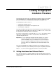
CHAPTER 1 Locating the Appropriate Installation Procedure This manual provides instructions for replacing the Regulator board in your installation with a GV3000/SE version 6 Regulator board. It is intended for qualified electrical personnel responsible for installing and programming the GV3000/SE drive.
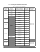
1.2 Locating the Installation Procedure Table 1.1 – Locating the Procedure for 460 VAC Drives Horsepower Rating 1 to 5 For Drive Model Number... Replace the Regulator Board with Part Number... Using the Procedure in Chapter... 1V41xx 1V44xx 0-56921-6xx 2 2V41xx 2V44xx 0-56921-6xx 2 3V41xx 3V44xx 0-56921-6xx 2 0-56921-6xx 2 0-56921-6xx 3 0-56921-6xx 3 0-56921-6xx 6 5V41xx 5V44xx 7V41xx 7.
Table 1.1 – Locating the Procedure for 460 VAC Drives (Continued) Horsepower Rating 75 to 200 200 to 400 For Drive Model Number... Replace the Regulator Board with Part Number... Using the Procedure in Chapter...
Table 1.2 – Locating the Procedure for 230 VAC Drives (Continued) Horsepower Rating 30 to 100 For Drive Model Number... Replace the Regulator Board with Part Number... Using the Procedure in Chapter... 30V20xx 0-56921-6xx 5 40V20xx 0-56921-6xx 5 50V20xx 0-56921-6xx 5 60V20xx 0-56921-6xx 5 75V20xx 0-56921-6xx 5 100V20xx 0-56921-6xx 5 Drive Software and Hardware Manuals SW: D2-3416 HW: D2-3417 Table 1.
CHAPTER 2 Installing Regulator Board P/N 0-56921-6xx in 1 to 5 HP @ 460 VAC Drives ! ATTENTION: Only qualified electrical personnel familiar with the construction and operation of this equipment and the hazards involved should install, adjust, operate, and/or service this equipment. Read and understand this manual and other applicable manuals in their entirety before proceeding. Failure to observe this precaution could result in severe bodily injury or loss of life.
Refer to figure 2.2 as you perform the procedure. Important: Read and understand the warning labels on the outside of the drive before proceeding. Step 1. Shut Down the Drive Step 1.1. Disconnect, lock out, and tag all incoming power to the drive. Step 1.2. Wait five minutes for the DC bus capacitors to discharge. Step 1.3. Remove the cover by loosening the four cover screws. Important: Read and understand the warning labels on the inside of the drive before proceeding. Step 2.
Option Board Regulator Board Top View SPEED Regulator Board Front View Side View Figure 2.
Step 3.4. Use a magnetic screwdriver to remove the three M4 x 10 screws that fasten the bottom of the keypad support bracket to the drive heat sink. Important: The bracket is connected to the drive by wiring. Do not attempt to lift the bracket out completely as this can damage or pull out wiring. Step 3.5. Spread the retaining clips on the 26-conductor Regulator board ribbon cable to disconnect it from the Current Feedback board. The Current Feedback board is located on the right below the keypad. Step 3.6.
Step 4.2. Drives with option boards only: Remove the option board from the keypad bracket. The option board is held in place by four fasteners. The option board fasteners might include plastic rivets. To remove a plastic rivet, pull the post from the rivet body. Remove the body of the rivet. Use a small pair of wire cutters or a similar tool to pry these pieces loose. Do not cut the rivets. Step 4.3. Drives with option boards only: Remove the Regulator board ribbon connector from the option board.
Step 5. Install the New Regulator Board in the Keypad Bracket Step 5.1. Remove the new Regulator board from its anti-static wrapper. Make sure the jumper settings on the new board match those on the old board. Step 5.2. Slide the new Regulator board into the keypad bracket. Position the board so that seven-segment displays appear in the display window in the keypad. Step 5.3. Connect the green-striped keypad ribbon cable to the new Regulator board.
Step 6.3. Inspect the Current Feedback board connector thoroughly for bent or misaligned pins. Step 6.4. Align the keypad support bracket with the mounting holes in the drive heat sink. Fasten the bracket with the three M4 x 10 screws removed earlier. Step 6.5. Align the Regulator board’s 26-conductor ribbon cable connector with the Current Feedback board connector. Press it in until it locks into position. Step 6.6.
2-8 GV3000/SE Drive Version 6 Regulator Board Installation Instructions
CHAPTER 3 Installing Regulator Board P/N 0-56921-6xx in 7.5 to 10 HP @ 460 VAC Drives ! ATTENTION: Only qualified electrical personnel familiar with the construction and operation of this equipment and the hazards involved should install, adjust, operate, and/or service this equipment. Read and understand this manual and other applicable manuals in their entirety before proceeding. Failure to observe this precaution could result in severe bodily injury or loss of life.
Step 1. Shut Down the Drive Step 1.1. Disconnect, lock out, and tag all incoming power to the drive. Step 1.2. Wait five minutes for the DC bus capacitors to discharge. Step 1.3. Remove the cover by loosening the four cover screws. Important: Read and understand the warning labels on the inside of the drive before proceeding. Step 2. Verify That the DC Bus Capacitors are Discharged Step 2.1. Use a voltmeter to verify that there is no voltage at the drive’s AC input power terminals (R/L1, S/L2, T/L3).
Important: The bracket is connected to the drive by wiring. Do not attempt to lift the bracket out completely as this can damage or pull out wiring. Step 3.5. Disconnect the green-striped ribbon cable from the Regulator board. This cable is located on the right side of the drive. To disconnect this cable, insert a small screwdriver inside the cable loop and press in on the retaining clip in the center of the connector while pulling out the connector. Refer to figure 3.2. Figure 3.
Step 4.2. Drives with option boards only: Remove the Regulator board ribbon connector from the option board. The connector is held in place by retaining clips. Spread these clips to release the connector. Step 4.3. Remove the old Regulator board from the keypad bracket. The board is fastened with two metal screws with lock washers and two plastic rivets. To remove a plastic rivet, pull the post from the rivet body. Remove the body of the rivet.
Current Feedback Board Option Board Regulator Board Top View Front View Side View Figure 3.4 – Regulator Board Location in 7.5 to 10 HP @ 460 VAC Drives Step 5.4. Connect the new Regulator board to the keypad bracket using the fasteners removed earlier. Use the metal screws and lock washers for the two corners of the board that have metal-plated grounding pads. Use the rivets to mount the other two corners of the board. To use the rivets, insert the plastic rivet bodies into the mounting holes.
Step 5.6. Drives with option boards only: Reconnect the option board to the keypad bracket using the fasteners removed earlier. Note any corners of the board that have metal-plated grounding pads. To properly ground the option board, use the metal screws and lock washers to mount the corners that have the grounding pads. If the option board fasteners included plastic rivets, insert the plastic rivet bodies into the mounting holes and press the posts into the rivet bodies.
CHAPTER 4 Installing Regulator Board P/N 0-56921-6xx in 1 to 20 HP @ 230 VAC Drives ! ATTENTION: Only qualified electrical personnel familiar with the construction and operation of this equipment and the hazards involved should install, adjust, operate, and/or service this equipment. Read and understand this manual and other applicable manuals in their entirety before proceeding. Failure to observe this precaution could result in severe bodily injury or loss of life.
Unless otherwise indicated, keep all hardware that is removed. You will need it for reassembly. This includes option boards, screws, lock washers, and rivets. Refer to figure 4.3 as you perform the procedure. Important: Read and understand the warning labels on the outside of the drive before proceeding. Step 1. Shut Down the Drive Step 1.1. Disconnect, lock out, and tag all incoming power to the drive. Step 1.2. Wait five minutes for the DC bus capacitors to discharge. Step 1.3.
Step 3. Remove the Keypad Bracket from the Drive Step 3.1. Record the wiring to the Regulator board terminal strip. Step 3.2. Disconnect the wiring from the Regulator board terminal strip. Step 3.3. Drives with option boards only: Record the wiring connections to the option board terminals. Disconnect this wiring from the option board terminal strip. Step 3.4. Use a magnetic screwdriver to remove the three M4 x 10 screws that fasten the keypad support bracket to the heat sink. Step 3.5.
Keypad Bracket Regulator Board Terminal Strip Power Terminal Strip Figure 4.3 – 1 to 20 HP @ 230 VAC GV3000/SE Drive Step 4. Remove the Regulator Board from the Keypad Bracket Step 4.1. Drives with option boards only: Remove the option board from the keypad bracket. The option board is held in place by four fasteners. The option board fasteners might include plastic rivets. To remove a plastic rivet, pull the post from the rivet body. Remove the body of the rivet.
USER DISPLAY J5 26-Pin Ribbon Cable 34-Pin Ribbon Cable J3 J9 J7 J8 J17 J4 USER I/O TERMINAL STRIP Figure 4.4 – Location of Jumpers J4 and J17 on the Regulator Board Step 5. Install the New Regulator Board in the Keypad Bracket Refer to figure 4.3 for component locations. Step 5.1. Remove the new Regulator board from its anti-static wrapper. Make sure the jumper settings on the new board match those on the old board. Step 5.2. Slide the new Regulator board into the keypad bracket.
Step 5.6. Drives with option boards only: Reconnect the option board to the keypad bracket using the fasteners removed earlier. Note any corners of the board that have metal-plated grounding pads. To properly ground the option board, use the metal screws and lock washers to mount the corners that have the grounding pads. If the option board fasteners included plastic rivets, insert the plastic rivet bodies into the mounting holes and press the posts into the rivet bodies.
CHAPTER 5 Installing Regulator Board P/N 0-56921-6xx in 30 to 100 HP @ 230 VAC and 75 to 200 HP @ 460 VAC Drives ! ATTENTION: Only qualified electrical personnel familiar with the construction and operation of this equipment and the hazards involved should install, adjust, operate, and/or service this equipment. Read and understand this manual and other applicable manuals in their entirety before proceeding. Failure to observe this precaution could result in severe bodily injury or loss of life.
Some steps are only required if an option board, such as the AutoMax Network option board, is installed. These steps are preceded by the text “Option board only.” Unless otherwise indicated, keep all hardware that is removed. You will need it for reassembly. This includes option boards, screws, lock washers, and rivets. Important: Read and understand the warning labels on the outside of the drive before proceeding. Step 1. Shut Down the Drive Step 1.1.
Step 3. Remove the Keypad Bracket From the Drive Refer to figure 5.2 as you perform the procedure. Figure 5.2 – Location of Terminal Cover and Regulator Board Cover in 30 to 100 HP @ 230 VAC and 75 to 200 HP @ 460 VAC Drives Step 3.1. If the drive has: • A Regulator board cover and terminal cover: Remove the three M4 screws from the Regulator board cover. Remove the cover. • A terminal cover only: If you have this type of drive, this procedure is easier to perform if you lay the drive on its side.
Step 3.9. Turn the Regulator board assembly over and remove the insulator from the keypad bracket by removing a fixing screw (with lock washer) and a rivet from the keypad bracket.
To remove a plastic rivet, pull the post from the rivet body. Remove the body of the rivet. Use a small pair of wire cutters or a similar tool to pry these pieces loose. Do not cut the rivets. Step 4.3. Drives with option boards only: Remove the Regulator board ribbon connector from the option board. The connector is held in place by retaining clips. Spread these clips to release the connector. Step 4.4. Slide the old Regulator board out of the keypad bracket. Step 4.5.
Step 5.4. Connect the new Regulator board to the keypad bracket using the fasteners removed earlier. Use the metal screws and lock washers for the two corners of the board that have metal-plated grounding pads. Use the rivets to mount the other two corners of the board. To use the rivets, insert the plastic rivet bodies into the mounting holes. Press the posts into the rivet bodies. Important: Improper grounding of the Regulator board can result in erratic operation of the drive. Step 5.5.
This completes the hardware installation of the Regulator board replacement procedure. Go to chapter 11 for the procedure to clear the CHS fault code.
CHAPTER 6 Installing Regulator Board P/N 0-56921-6xx in 15 to 25 HP and 25 to 60 HP @460 VAC Drives ! ATTENTION: Only qualified electrical personnel familiar with the construction and operation of this equipment and the hazards involved should install, adjust, operate, and/or service this equipment. Read and understand this manual and other applicable manuals in their entirety before proceeding. Failure to observe this precaution could result in severe bodily injury or loss of life.
If the drive is panel-mounted, this procedure will be easier to perform if the drive is removed from the panel. Some steps are only required if an option board, such as the AutoMax Network option board, is installed. These steps are preceded by the text “Option board only.” Unless otherwise indicated, keep all hardware that is removed. You will need it for reassembly. This includes option boards, screws, lock washers, and rivets.
Step 2. Verify That the DC Bus Capacitors are Discharged Step 2.1. Use a voltmeter to verify that there is no voltage at the drive’s AC input power terminals (R/L1, S/L2, T/L3). Step 2.2. Ensure that the DC bus capacitors are discharged. To check DC bus potential: a. Stand on a non-conductive surface and wear insulated gloves. b. Use a voltmeter to measure the DC bus potential at the DC bus power terminals as shown in figures 6.3 (15 to 25 HP) and 6.4 (25 to 60 HP).
DC Bus Volts + D1 Input Wiring R/L1 S/L2 RV2 T/L3 RV3 Figure 6.4 – DC Bus Voltage Terminals (25 to 60 HP @ 460 VAC Drives) ! Step 3. ATTENTION: The drive contains printed circuit boards that are static-sensitive. An anti-static wristband should be worn by any person who touches the drive components, connectors, or wiring. Erratic machine operation and damage to, or destruction of, equipment can result if this precaution is not followed. Remove the Keypad Bracket from the Drive Step 3.1.
Figure 6.5 – Disconnecting the Keypad Ribbon Cable from the Regulator Board Step 4. Remove the Regulator Board from the Keypad Bracket Step 4.1. Drives with option boards only: Remove the option board from the keypad bracket. The option board is held in place by four fasteners. The option board fasteners might include plastic rivets. To remove a plastic rivet, pull the post from the rivet body. Remove the body of the rivet. Use a small pair of wire cutters or a similar tool to pry these pieces loose.
USER DISPLAY J5 26-Pin Ribbon Cable 34-Pin Ribbon Cable J3 J9 J7 J8 J17 J4 USER I/O TERMINAL STRIP Figure 6.6 – Location of Jumpers J4 and J17 on the Regulator Board Step 5. Install the New Regulator Board in the Keypad Bracket Refer to figure 6.1 or 6.2 for component locations. Step 5.1. Remove the new Regulator board from its anti-static wrapper. Make sure the jumper settings on the new board match those on the old board. Step 5.2. Slide the new Regulator board into the keypad bracket.
Step 5.6. Drives with option boards only: Reconnect the option board to the keypad bracket using the fasteners removed earlier. Note any corners of the board that have metal-plated grounding pads. To properly ground the option board, use the metal screws and lock washers to mount the corners that have the grounding pads. If the option board fasteners included plastic rivets, insert the plastic rivet bodies into the mounting holes and press the posts into the rivet bodies.
6-8 GV3000/SE Drive Version 6 Regulator Board Installation Instructions
CHAPTER 7 Installing Regulator Board P/N 413338-6BU in 25 to 50 HP @ 460 VAC Drives ! ATTENTION: Only qualified electrical personnel familiar with the construction and operation of this equipment and the hazards involved should install, adjust, operate, and/or service this equipment. Read and understand this manual and other applicable manuals in their entirety before proceeding. Failure to observe this precaution could result in severe bodily injury or loss of life.
Step 1. Shut Down the Drive Step 1.1. Disconnect, lock out, and tag all incoming power to the drive. Step 1.2. Wait five minutes for the DC bus capacitors to discharge. Step 1.3. Remove the cover by loosening the six cover screws. Important: Read and understand the warning labels on the inside of the drive before proceeding. Keypad Regulator Board Power Module Interface Board Figure 7.
Step 2. Verify That the DC Bus Capacitors are Discharged Step 2.1. Using a voltmeter, verify that there is no voltage at the drive’s AC input power terminals (1L1, 1L2, 1L3). Step 2.2. Remove the two screws from the top of the hinged panel on which the keypad bracket is mounted. Tilt the mounting panel forward out of the drive chassis. Step 2.3. Ensure that the DC bus capacitors are discharged. To check DC bus potential: a. Stand on a non-conductive surface and wear insulated gloves. b.
! Step 3. ATTENTION: The drive contains printed circuit boards that are static-sensitive. An anti-static wristband should be worn by any person who touches the drive components, connectors, or wiring. Erratic machine operation and damage to, or destruction of, equipment can result if this precaution is not followed. Remove the Keypad Bracket from the Drive Step 3.1. Swing the hinged mounting panel back into position in the drive chassis. Step 3.2. Record the wiring to the Regulator board terminal strip.
Step 4. Remove the Regulator Board from the Keypad Bracket Step 4.1. Drives with option boards only: Remove the Regulator board ribbon connector from the option board. The connector is held in place by retaining clips. Spread these clips to release the connector. Step 4.2. Drives with option boards only: Remove the option board from the keypad bracket. Step 4.3. Remove the Regulator board from the keypad bracket by removing the four screws and hex nuts. Slide the old Regulator board out of the bracket.
Step 5.5. Drives with option boards only: Remount the option board to the keypad bracket using the four screws removed earlier. Step 5.6. Route the new Regulator board’s 60-conductor ribbon cable through the slot in the hinged mounting panel to the connector on the Power Unit Interface board. Align the two connectors. Placing your thumb beneath the Power Unit board for support, carefully press the ribbon cable connector in until it locks into position. Step 6.
CHAPTER 8 Installing Regulator Board P/N 413338-6BU in 60 to 100 HP and 100 to 150 HP @ 460 VAC Drives ! ATTENTION: Only qualified electrical personnel familiar with the construction and operation of this equipment and the hazards involved should install, adjust, operate, and/or service this equipment. Read and understand this manual and other applicable manuals in their entirety before proceeding. Failure to observe this precaution could result in severe bodily injury or loss of life.
Important: Read and understand the warning labels on the outside of the drive before proceeding. Step 1. Shut Down the Drive Step 1.1. Disconnect, lock out, and tag all incoming power to the drive. Step 1.2. Wait five minutes for the DC bus capacitors to discharge. Step 1.3. Remove the cover by removing the six cover screws. Important: Read and understand the warning labels on the inside of the drive before proceeding. 45 47 Keypad Regulator Board Power Module Interface Board Figure 8.
Keypad Power Module Interface Board Regulator Board Figure 8.
Step 2. Verify That the DC Bus Capacitors are Discharged Step 2.1. Using a voltmeter, verify that there is no voltage at the drive’s AC input power terminals (1L1, 1L2, 1L3). Step 2.2. Loosen the two screws from the top of the hinged mounting panel on which the keypad bracket is mounted. Tilt the mounting panel forward out of the drive chassis. Step 2.3. Ensure that the DC bus capacitors are discharged. To check DC bus potential: a. Stand on a non-conductive surface and wear insulated gloves. b.
ATTENTION: The drive contains printed circuit boards that are static-sensitive. An anti-static wristband should be worn by any person who touches the drive components, connectors, or wiring. Erratic machine operation and damage to, or destruction of, equipment can result if this precaution is not followed.
Step 3.5. Disconnect the green-striped ribbon cable from the Regulator board. This cable is located on the right side of the drive. To disconnect this cable, insert a small screwdriver inside the cable loop and press in on the retaining clip in the center of the connector while pulling out the connector. See figure 8.5. Figure 8.5 – Disconnecting the Keypad Ribbon Cable from the Regulator Board Step 3.6.
Step 4. Remove the Regulator Board from the Keypad Bracket Step 4.1. Drives with option boards only: Remove the option board from the keypad bracket. The option board is held in place by four fasteners. Step 4.2. Drives with option boards only: Remove the Regulator board ribbon connector from the option board. The connector is held in place by retaining clips. Spread these clips to release the connector. Step 4.3. Remove the Regulator board from the keypad bracket by removing the four screws and hex nuts.
Step 5.5. Drives with option boards only: Remount the option board to the keypad bracket using the fasteners removed earlier. Step 6. Reinstall the Keypad Bracket Step 6.1. Reattach the keypad bracket to the hinged mounting panel using the four screws and lock washers removed earlier. Step 6.2. 100 to 150 HP drives only: Remove the tie that was fastened to the Power Module Interface board earlier.
CHAPTER 9 Installing Regulator Board P/N 0-56940-6xx in 200 to 400 HP @ 460 VAC Drives ! ATTENTION: Only qualified electrical personnel familiar with the construction and operation of this equipment and the hazards involved should install, adjust, operate, and/or service this equipment. Read and understand this manual and other applicable manuals in their entirety before proceeding. Failure to observe this precaution could result in severe bodily injury or loss of life.
Important: Read and understand the warning labels on the outside of the drive before proceeding.
! Step 3. ATTENTION: The drive contains printed circuit boards that are static-sensitive. An anti-static wristband should be worn by any person who touches the drive components, connectors, or wiring. Erratic machine operation and damage to, or destruction of, equipment can result if this precaution is not followed. Remove the Keypad Bracket from the Drive Refer to figure 9.1 for component locations. Step 3.1. Record the wiring to the Regulator board terminal strip. Step 3.2.
Step 4.9. Close and secure the outer cabinet door of the drive. Step 4.10. Remove the lockout and tag. Apply power to the drive. SELF is displayed while the drive performs power-up diagnostics. When diagnostics are complete, the fault code CHS will be displayed. This completes the hardware installation of the Regulator board replacement procedure. Go to chapter 11 for the procedure to clear the CHS fault code.
CHAPTER 10 Installing Regulator Board P/N 814.61.00 in 2 to 15 Amp and 24 to 30 Amp GV3000/SE Bookshelf Drives ! ATTENTION: Only qualified electrical personnel familiar with the construction and operation of this equipment and the hazards involved should install, adjust, operate, and/or service this equipment. Read and understand this manual and other applicable manuals in their entirety before proceeding. Failure to observe this precaution could result in severe bodily injury or loss of life.
This procedure requires access to the right side of the drive. Remove the drive from the panel if necessary. Unless otherwise indicated, keep all hardware that is removed. You will need it for reassembly. This includes screws, lock washers, and rivets. Important: Read and understand the warning labels on the outside of the drive before proceeding. Step 1. Shut Down the Drive Step 1.1. Disconnect, lock out, and tag all incoming power to the drive. Step 1.2.
Regulator Board Cover Screw Breakout Panel AC Input Power Terminals (L1, L2, L3) DC Bus Measuring Point (–)45, (+)47 Figure 10.1 – 2 to 15 Amp GV3000/SE Bookshelf Drive Installing Regulator Board P/N 814.61.
Regulator Board Cover Screw Front Panel Screws Breakout Panel Figure 10.
Keypad/Display Cable Connector Power Module Feedback Connector Regulator Board Regulator Board Ribbon Cable AC Input Power Terminals (L1, L2, L3) DC Bus Measuring Points (–)45, (+)47 Figure 10.3 – 24 to 30 Amp GV3000/SE Bookshelf Drive (Cover and Front Panel Removed) ! Step 3. ATTENTION: The drive contains printed circuit boards that are static-sensitive. An anti-static wristband should be worn by any person who touches the drive components, connectors, or wiring.
Step 5. Install the New Regulator Board in the Drive Step 5.1. Remove the new Regulator board from its anti-static wrapper. Make sure the jumper settings on the new board match those on the old board. See figure 10.4 for jumper locations. Power Module Feedback Connector (X16) Keypad/Display Cable Connector (X9) J17 V In C In V Out C Out J4 Analog Output Default: Voltage Analog Input Default: Voltage Terminal Strip (X1) Option Board Connector (X3) Figure 10.
Step 7. Reattach the Cover Step 7.1. Reconnect the keypad/display cable to the cover. Important: For 24 to 30 amp drives, fold and slide the keypad/display cable under the heatsink at the top of the drive before attaching the cover. Step 7.2. Reattach the cover using the single faceplate screw. Step 8. Reconnect the Cable Leads and Apply Power Step 8.1. Reconnect all cable leads to the appropriate terminals on the face of the drive. Step 8.2. Remove the lockout and tag. Apply power to the drive.
10-8 GV3000/SE Drive Version 6 Regulator Board Installation Instructions
CHAPTER 11 Clearing the CHS Fault Code and Identifying the Power Module ! ATTENTION: The Power Module identification procedure enabled in parameter P.998 clears the contents of parameter P.999. Only qualified electrical personnel who understand the potential hazards involved should make modifications to parameters P.998 and P.999. Failure to observe this precaution could result in damage to, or destruction of, the equipment. ATTENTION: Entering incorrect values into parameter P.
Step 2. Release the keys. 38 SPEED VOLTS AMPS Hz Kw TORQUE Password STOP RESET PUn flashes. RUNNING REMOTE JOG AUTO FORWARD AUTO MAN Forward Reverse Program RUN JOG REVERSE PROGRAM START ENTER RELIANCE ELECTRIC Step 3. Press the PROGRAM key. 3 SPEED VOLTS AMPS Hz Kw TORQUE Password STOP RESET RUNNING AUTO MAN Forward Reverse Program RUN JOG REMOTE JOG AUTO FORWARD REVERSE PROGRAM START The PROGRAM LED is on, and the First Menu General (P) parameters can be accessed.
Step 6. Press the ENTER key. SPEED VOLTS AMPS Hz Kw TORQUE Password STOP RESET RUNNING REMOTE JOG AUTO FORWARD Zero is displayed. AUTO MAN Forward Reverse Program RUN JOG REVERSE ENTER PROGRAM START RELIANCE ELECTRIC Step 7. Press the ▲ key until the password, 75, is displayed. ATTENTION: It is the user’s responsibility to determine how to distribute this password. Reliance Electric is not responsible for unauthorized access violations within the user’s organization.
Step 10. Press the ▲ key to enable the Power Module identification procedure. 2 SPEED VOLTS AMPS Hz Kw TORQUE Password STOP RESET RUNNING REMOTE JOG AUTO FORWARD On is displayed. AUTO MAN Forward Reverse Program RUN JOG REVERSE ENTER PROGRAM START RELIANCE ELECTRIC Step 11. Press the ENTER key.
Step 13. Press the ▲ key until the appropriate Power Module voltage and horsepower is displayed. SPEED VOLTS AMPS Hz Kw TORQUE Password STOP RESET RUNNING REMOTE JOG AUTO FORWARD AUTO MAN Forward Reverse Program RUN JOG REVERSE ENTER PROGRAM START RELIANCE ELECTRIC Sample display. Your display may be different. The Power Module values are displayed in the format V.nnn, where V represents the drive’s voltage rating, and nnn represents horsepower.
11.1 Verifying the Power Module Identification Value Using P.099 The value in P.999 is displayed in Second Menu General parameter P.099 (Power Module Type). Use this procedure to view P.099 and make sure it contains the correct value. Step 1. Press the PROGRAM key. 3 SPEED VOLTS AMPS Hz Kw TORQUE Password STOP RESET RUNNING AUTO MAN Forward Reverse Program RUN JOG REMOTE JOG AUTO FORWARD REVERSE PROGRAM START The PROGRAM LED is on, and First Menu (P) parameters can be accessed.
Step 5. Press the ▲ key until the password, 107, is displayed. ATTENTION: It is the user’s responsibility to determine how to distribute this password. Reliance Electric is not responsible for unauthorized access violations within the user’s organization. Failure to observe this precaution could result in damage to, or destruction of, the equipment. ! L SPEED VOLTS AMPS Hz Kw TORQUE Password STOP RESET RUNNING REMOTE JOG AUTO FORWARD This password enables access to the Second Menu parameters.
Step 8. Press the ENTER key to access parameter P.099. SPEED VOLTS AMPS Hz Kw TORQUE Password STOP RESET RUNNING REMOTE JOG AUTO FORWARD AUTO MAN Forward Reverse Program RUN JOG The display shows the value that was either automatically identified by the system or manually selected. REVERSE PROGRAM START ENTER RELIANCE ELECTRIC Sample display only. Your display may be different. Step 9. Refer to appendix A to verify that the value displayed is correct for your drive.
CHAPTER 12 Restoring the Drive Configuration After the Regulator board has been replaced, the drive powers up with the parameters set to their factory-default values. If you changed any of the parameters from their default values prior to replacing the board, you must change them again after you have completed the Power Module identification procedure described in chapter 11.
12-2 GV3000/SE Drive Version 6 Regulator Board Installation Instructions
CHAPTER 13 Troubleshooting the Installation Table 13.1 describes possible installation problems and actions required to correct them. The drive hardware reference manual also contains guidelines for troubleshooting the drive. Table 13.1 – Possible Problems and Corrective Actions Troubleshooting the Installation Description of Problem Corrective Action Replacement board is too big or too small. Check the part number on the replacement board. Use table 1.1, 1.2, or 1.
13-2 GV3000/SE Drive Version 6 Regulator Board Installation Instructions
APPENDIX A Power Module Identification Values for P.099/P.999 Table A.1 – P.009/P.999 Values for 230 VAC GV3000/SE Drives Horsepower (HP) Model Number P.099/P.999 Value 1 1V21xx 1V24xx 2.001 2 2V21xx 2V24xx 2.002 3 3V21xx 3V24xx 2.003 5 5V21xx 5V24xx 2.005 7.5 7V21xx 7V22xx 2.007 10 10V21xx 10V22xx 2.010 15 15V21xx 15V22xx 2.015 20 20V21xx 20V22xx 2.020 30 30V20xx 2.030 40 40V20xx 2.040 50 50V20xx 2.050 60 60V20xx 2.060 75 75V20xx 2.075 100 100V20xx 2.
Table A.2 – P.009/P.999 Values for 460 VAC GV3000/SE Drives A-2 Horsepower (HP) Model Number P.099/P.999 Value 1 1V41xx 1V44xx 4.001 2 2V41xx 2V44xx 4.002 3 3V41xx 3V44xx 4.003 5 5V41xx 5V44xx 4.005 7.5 7V41xx 7V42xx 4.007 10 10V41xx 10V42xx 4.010 15 15V41xx 15V42xx 4.015 20 20V41xx 20V42xx 4.020 25 25G41xx 25G42xx 4.025 25 25V41xx 25V42xx 4.026 30 30V41xx 30V42xx 4.030 30 30R41xx 30T41xx 40 40V41xx 40V42xx 4.040 50 50V41xx 50V42xx 4.050 50 50R41xx 50T41xx 4.
Table A.2 – P.009/P.999 Values for 460 VAC GV3000/SE Drives (Continued) Horsepower (HP) Model Number P.099/P.999 Value 125 125R41xx 4.150 150 150V40xx 4.151 200 200V41xx 4.200 200 200V40xx 4.201 250 250V41xx 4.250 300 300V41xx 4.300 350 350G41xx 4.350 350 350V41xx 4.351 400 400V41xx 4.400 Table A.3 – P.009/P.999 Values for GV3000/SE Bookshelf Drives Rating Model Number P.099/P.999 Value 3.1 A 31ER40xx 31ER40xx 3.001 3.8 A 38ER40xx 38ET40xx 3.002 5.
U.S. Drives Technical Support Tel: (1) 262.512.8176, Fax: (1) 262.512.2222, Email: support@drives.ra.rockwell.com, Online: www.ab.com/support/abdrives Trademarks not belonging to Rockwell Automation are property of their respective companies. Publication D2-3369 – November 1998 Copyright © 1998 Rockwell Automation, Inc. All Rights Reserved. Printed in USA.